TLC556: TLC556

Part Number: TLC556
Other Parts Discussed in Thread: NA555, , TPL5110, LM339, TLV4082, TPL5111

Tool/software:

Desired function waveform.pdfNA555, NE555, SA555, SE555 Precision Timers (Rev. I).pdf

Hello

 I forgot to include some information in my last email.  Please use this email. 


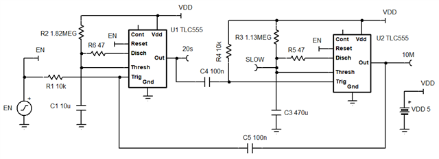
I am designing a PCB for what our company hopes to be a large volume application.   First, I want to test the circuit .  I have a question regarding the TLC556 timer and would appreciate your help as soon as possible so that I can submit my design to the layout team.  I have attached my questions in the pdf called " Desired Function Waveform" . I also attached the TI datasheet that I have been working from.  I am thinking of using a variation of Figure 22 from the attached datasheet, but I am not sure how the timer will start up.  See attached PDF of what I need to build.


  • Hello Robert, welcome to the TI e2e forums.

    In circuit below, EN low stops both timers. When EN goes high, U1 goes high for 20 seconds. U1 going low starts (10min-20s) U2 timer. When U2 is done, it triggers U1 for another 20 second pulse. R5, R6 are optional to slow down (reduce peak current) for the timing cap discharges. Not shown are CONT and supply bypass capacitors. Also add 1N4148 diode from TRIG to VDD (suggested in figure 25 of data sheet). Accuracy will be based on the the performance of the timing capacitors.

    20s every 10min.TSC

    Also consider using a nano power timers such as TPL5110 which do need need large timing capacitors. Start a related thread using that part number to see how that could be done.

  • Hello Ron,

    Thank you so very  much for your solution using the TLC556.  You must have ESP, because what I did not tell you is that I will be powering this circuit using two AAA batteries.  Therefore, power consumption is critical to achieve longer battery life.  Use of the TPL 5110 (which I did not previously know existed) would be preferable.  Would you be able to and so kind as to provide a circuit using the TPL 5110 that performs the same function as the circuit you proposed using the TLS556.   Also we hope to be making this product in high volume. Do you think the TPL5110 will be in production for many years? I know the 556 has been around for a long time?

    In addition, to the timer I am using an LM339 quad comparator in the circuit.  The application only needs 2 comparators, but I want to minimize the number of packages on the pcb as well as minimizing power consumption. I though the LM339 would be a good low power choice.  Do you have any other recommendations.

    I sincerely thank you again for all your help.

    Robert Bishop

  • Robert,

    For comparators and two AAA batteries that are many better choices. TLV7024 dual comp and  TLV4082 dual comp with internal reference voltage. 

    TPL5110 is not in my group, (that why I suggested asking related question). I'll transfer this post to that group. 

  • Hi Robert,

    See response in the latest post.

    e2e.ti.com/.../tpl5110-tpl5110

  • Hello Ron

    I have now looked at other alternatives and have decided to go with the circuit that you suggested above using the TLC556. I now have two questions regarding your suggested circuit.

    Question 1: You said that in your circuit U1 goes high when the ENABLE signal goes high, which is what I want.  But the data sheet for the TLC556 says that the 556 is triggered by a negative going pulse( ie when the level goes below 1/3 vcc).   Can you please explain?

    Question 2:  The vast majority of the time the 556 will be held in reset.  What is the approximate power consumption (supply current when the TLC556 is held in reset 

    Thank you for all your help.

    Robert

  • Robert,

    You will need two TPL5110. Perhaps plus some logic help that can be low power at DC. One can do 20 seconds one 10 minutes 

    A1)  Yes it is you say. RESET is high and TRIG is LOW for a short time.

    A2) RESET is output low it is not a shutdown state. No power savings. TLC566 is not the solution you need. 

  • Hello Ron

    I am unable to read or understand your response regarding the TPL5111.  The top have of the table is missing, and no circuit is provided. 

    1. Can you kindly provide a circuit diagram using the two TPL5111 chips.

    2. Regarding your previous suggestion and TLC556 circuit diagram.  I have an idea.  If I connect signal Enable (active high)  to the reset pin of the 556 ( this removes the reset condition when ENABLE goes high) and also connect the invert of ENABLE through an RC to the trigger input so than the trigger input goes low slightly after RESET goes high, I think the TIC556 circuit will work.

    3.  I would be interested in a circuit using two TPL5111 because it would use much less power