LMX2820: may lose lock if the same configuration is set multiple times

Part Number: LMX2820

Tool/software:

Hi,

We’ve encountered a similar issue while continuously sweeping the output frequency from 13 GHz to 20 GHz in 100 MHz steps, with a dwell time of 500 ms per step. Around the 400th iteration, the device consistently loses lock.

When this happens, toggling the RESET pin and reinitializing the device restores normal operation. However, we’re looking for a more robust solution to prevent this lock loss altogether.

Has anyone found a way to mitigate this behavior during high-frequency sweeping?

Thanks in advance!

Here’s the register sequence we’re using for each frequency update:

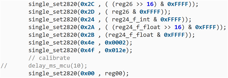
the register values:

R122	0x7A0000
R121	0x790000
R120	0x780000
R119	0x770000
R118	0x760000
R117	0x750000
R116	0x740000
R115	0x730000
R114	0x720000
R113	0x710000
R112	0x70FFFF
R111	0x6F0000
R110	0x6E001F
R109	0x6D0000
R108	0x6C0000
R107	0x6B0000
R106	0x6A0000
R105	0x69000A
R104	0x680014
R103	0x670014
R102	0x660028
R101	0x6503E8
R100	0x640533
R99	0x6319B9
R98	0x621C80
R97	0x610000
R96	0x6017F8
R95	0x5F0000
R94	0x5E0000
R93	0x5D1000
R92	0x5C0000
R91	0x5B0000
R90	0x5A0000
R89	0x590000
R88	0x5803FF
R87	0x57FF00
R86	0x560040
R85	0x550000
R84	0x540040
R83	0x530F00
R82	0x520000
R81	0x510000
R80	0x5001C0
R79	0x4F010E
R78	0x4E0002
R77	0x4D0708
R76	0x4C0000
R75	0x4B0000
R74	0x4A0000
R73	0x490000
R72	0x480000
R71	0x470000
R70	0x46000E
R69	0x450011
R68	0x440000
R67	0x430000
R66	0x42003F
R65	0x410000
R64	0x400084
R63	0x3FC350
R62	0x3E0000
R61	0x3D03E8
R60	0x3C01F4
R59	0x3B1388
R58	0x3A0000
R57	0x390001
R56	0x380001
R55	0x370002
R54	0x360000
R53	0x350000
R52	0x340000
R51	0x33203F
R50	0x320080
R49	0x310000
R48	0x304180
R47	0x2F0300
R46	0x2E0300
R45	0x2D0002
R44	0x2C8000
R43	0x2B6501
R42	0x2A1DCD
R41	0x290000
R40	0x280000
R39	0x27CA01
R38	0x263B9A
R37	0x250500
R36	0x240020
R35	0x233180
R34	0x220010
R33	0x210000
R32	0x201241
R31	0x1F0401
R30	0x1EB18C
R29	0x1D318C
R28	0x1C0639
R27	0x1B8001
R26	0x1A0DB0
R25	0x190624
R24	0x180E34
R23	0x171102
R22	0x16E2BF
R21	0x151C64
R20	0x14272C
R19	0x132120
R18	0x1203E8
R17	0x111440
R16	0x102712
R15	0x0F2001
R14	0x0E3001
R13	0x0D0038
R12	0x0C0408
R11	0x0B0612
R10	0x0A0000
R9	0x090005
R8	0x08C802
R7	0x0700C8
R6	0x060A43
R5	0x053832
R4	0x044204
R3	0x030041
R2	0x0281F4
R1	0x01D7A0
R0	0x006470

  • Hi Yingju,

    There is a small percentage that VCO doubler calibration may fail and when failure happen, we have to reset the device and start over again.

    If your application requires changing the output frequency from time to time, you can either operate the device in full assist mode or use InstCal, both approaches skip calibration and therefore avoid losing lock due to VCO doubler calibration.

    InstCal is more easy to use, in my opinion. To use InstCal, we will do a one-time calibration. After that, changing frequency does not require calibration anymore, simply program the frequency related registers and the device will lock to the desired frequency.

    In addition to the frequency related registers, full assist mode requires programming a few additional VCO and VCO doubler related registers. A one-time calibration for each desired frequency is required to gather the VCO can VCO doubler register information. More on full assist is available here: https://www.ti.com/lit/pdf/snaa336

    Let me know how you would like to proceed, I could provide more instruction on the operation.

  • Hi Noel,

    Thank you for the quick reply. I’d like to start with full assist mode. I have a couple of questions:

    1. How do I perform the initial auto calibration to gather the required VCO and VCO doubler register values?
    2. How long does it typically take to change frequencies (including the auto calibration time)?
  • Hi Yingju,

    You will only need auto calibration during the LUT creation, frequency lock time should not be an issue. Lock time depends on configuration, it could vary between XXµs to XXXµs. During the LUT creation, you may assume the lock time is 1ms for any frequency chagne.

    Here is the procedure for full assist operation.

    LUT creation
    1. Program the device to the desire frequency without any calibration assist
    2. Read back rb_VCO_SEL, rb_VCO_CAPCTRL and rb_VCO_DACISET
    3. Read back rb_DBLR1_PD_RB (R113[14]), rb_DBLR2_PD_RB (R113[15])
    4. If rb_DBLR1_PD_RB = 0, read back:
    - rb_DBLR1_AMP1_DACCTRL (R115[8:7])
    - rb_DBLR1_AMP2_DACCTRL (R115[10:9])
    - rb_DBLR1_AMP3_DACCTRL (R115[12:11])
    - rb_DBLR1_PREGEN_AMP_DACCTRL (R115[15:13])
    - rb_DBLR1_PREGEN_AMP_CAPCTRL (R116[11:8])
    - rb_DBLR1_AMP_CAPCTRL (R116[3:0])
    If rb_DBLR2_PD_RB = 0, read back:
    - rb_DBLR2_AMP1_DACCTRL (R114[15:14])
    - rb_DBLR2_AMP2_DACCTRL (R115[1:0])
    - rb_DBLR2_AMP3_DACCTRL (R115[3:2])
    - rb_DBLR2_PREGEN_AMP_DACCTRL (R115[6:4])
    - rb_DBLR2_PREGEN_AMP_CAPCTRL (R116[15:12])
    - rb_DBLR2_AMP_CAPCTRL (R116[7:4])
    5. Repeat step 1 to 4 for all the frequency of interest
    Apply the data
    6. Default the following settings
    - FCAL_EN = 0
    - VCO_CAPCTRL_FORCE, VCO_SEL_FORCE, VCO_DACISET_FORCE = 1
    - DBLBUF_PLL_EN, DBLBUF_CHDIV_EN, DBLBUF_OUTBUF_EN, DBLBUF_OUTMUX_EN = 1
    - DBLR_PATH_OVRD, R83[1] = 1
    - DBLR_AMP_CAPCTRL_OVRD, R83[2] = 1
    - DBLR_AMP_DACCTRL_OVRD, R83[3] = 1
    - DBLR_PREGEN_AMP_CAPCTRL_OVRD, R83[4] = 1
    - DBLR_PREGEN_AMP_DACCTRL_OVRD, R83[5] = 1
    7. Program frequency related registers
    8. Program VCO_CAPCTRL, VCO_SEL and VCO_DACISET according to the read back value
    9. If rb_DBLR1_PD_RB = 0, set DBLR1_PD = 0 (R83[11]) and DBLR2_PD = 1 (R84[6]). Then write the read back value to the following fields:
    - DBLR1_AMP_CAPCTRL, R86[10:7]
    - DBLR1_PREGEN_AMP_CAPCTRL, R87[3:0]
    - DBLR1_PREGEN_AMP_DACCTRL, R88[6:4]
    - DBLR1_AMP1_DACCTRL, R87[9:8]
    - DBLR1_AMP2_DACCTRL, R87[11:10]
    - DBLR1_AMP3_DACCTRL, R87[13:12]
    If rb_DBLR2_PD_RB = 0, set DBLR1_PD = 1 and DBLR2_PD = 0. Then write the read back value to the following fields:
    - DBLR2_AMP_CAPCTRL, R86[14:11]
    - DBLR2_PREGEN_AMP_CAPCTRL, R87[7:4]
    - DBLR2_PREGEN_AMP_DACCTRL, R88[9:7]
    - DBLR2_AMP1_DACCTRL, R87[15:14]
    - DBLR2_AMP2_DACCTRL, R88[1:0]
    - DBLR2_AMP3_DACCTRL, R88[3:2]
    10. Program R0