This thread has been locked.

If you have a related question, please click the "Ask a related question" button in the top right corner. The newly created question will be automatically linked to this question.

LMK05318: LMK05318 EEPROM programm

Part Number: LMK05318
Other Parts Discussed in Thread: USB2ANY,

Can LMK05318 be programmed internally via the TICS Pro in one step?I connected the TICS pro to the FT2232 USB-to-SPI programmer, but found that there was no effect at all.Could you please provide a method for programming the internal EEPROM of LMK05318 using the FT2232 programmer via TICS pro?

  • Hi, 

    LMK05318 EEPROM can be programmed using TICS Pro and a USB2ANY dongle. Are you programming these devices on an EVM, or is this on your own hardware? 

    If you have some way to automate register writes on the FT2232 programmer, TICS Pro can export the EEPROM programming sequence for your configuration (EEPROM page -> Export EEPROM instructions). 

  • Hi,

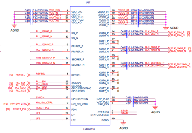
        I use my own hardware board.My design has reserved the SPI interface of LMK05318, as shown in the following screenshot. I am using USB2ANY to connect LMK05318 through the SPI interface.but I don't know how to program the internal EEPROM.Could you please guide me on how to program the internal EEPROM of LMK05318 using USB2ANY?

  • Hi Chen, 

    If you've already connected a USB2ANY to your hardware, the most straightforward approach is to program the EEPROM directly in the TICS Pro GUI. On the "EEPROM" page in the GUI, you can click on "Program EEPROM" to write the config loaded in the GUI to the device EEPROM. I've attached a screenshot of the relevant page in the GUI for reference. To verify that the EEPROM was successfully programmed, you can power cycle the device and readback the EEPROM status, you should see the value for NVMCNT increment by one. Let me know if you run into any issues getting this working on your end. 

  • HI Connor,

         The interface of my T TICS Pro GUI is different from yours. Please see the screenshot below.Is this because of the version of the TICS Pro GUI software?Do I need to update the version?

  • HI Connor,

          The device I'm using is LMK05318, while your TICS Pro GUI interface uses LMK05318B. Therefore, the interface is different. Could you guide me on how to configure LMK05318 in the TICS Pro GUI interface?

  • Hi Chen, 

    Thanks for the clarification here. LMK05318 (non-B version) is a previous silicon revision but for the most part it is software compatible with the newer "B" revision. For new designs I do recommend using the "B" version if possible. You can refer to this E2E post for more information on the differences:  LMK05318B: The difference between LMK05318B and LMK05318(without -B) 

    In the LMK05318 (non-B) GUI, you should be able to program the EEPROM by clicking the "Commit registers & Extra bytes -> Chip SRAM"  and then the "Program EEPROM <- SRAM" buttons. Alternatively you can press the "Program EEPROM" button in the top toolbar which should be equivalent programming. Let me know if this works on your end. 

  • HI Connor,

          I have already tried the method you suggested for programming the internal EEPROM.But I found that there was still no clock output signal at all.Could you please help me check if there are any issues with my configuration file?

    LMK05318_20260512.tcs

  • Hi Chen, 

    Have you verified that the XO input is present? Are the clock outputs enabled if you click "write all registers" with your config loaded in TICS Pro? I'm just trying to verify that this is an issue with the EEPROM programming rather than some other issue with the config, hardware, etc. 

    One thing I noticed in the config is that the DPLL won't be able to lock to the 100MHz PRIREF input since VCO1 does not have a fractional relationship with the XO frequency (2500MHZ VCO frequency / 25MHz XO frequency = 100). I would recommend disabling MUTE_DPLL_FRLOCK on the outputs page just to make sure that the outputs aren't muted since the DPLL will never be able to lock. 

  • Hi Connor,

           Measuring the input of the XO crystal oscillator, it was found to be present.When I clicked to "write all  registers", I measured the clock output of the measurement board, but failed to measure the clock output signal.

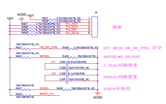
           Currently, there are no two-channel reference clock inputs for DPLL on my board.Only a 25M crystal input signal is available.I only want to use the APLL mode.The complete circuit is shown in the following screenshot.


  • Hi Chen, 

    Thanks for confirming that only the APLL is being used here. I looked through the .tcs config again and I did notice a few things which could prevent the APLLs from locking properly, which could be keeping the outputs muted. I made the following changes to the config: 

    MUTE_DPLL_FRLOCK: 1 -> 0 

    PLL2_RBLEED_CP: Changed from open (no resistance) to 766.96 Ohms

    PLL2 lock wait time: Changed from 300us to 3ms

    PLL1_LF_R2: Changed from 2505 Ohms to 414 Ohms

    Can you try out the attached config and see if the outputs look as expected? 

    LMK05318_20260512_Updated.tcs

  • Hi Connor,

         Thank you for sending me the PLL configuration file.I am using your configuration file to program the PLL.

          At the same time, I also identified the root cause of the problem.This should be caused by the "PDN" pin.In my design, no capacitors were added to the "PDN" pins to form a capacitive-resistive reset circuit.Therefore, the PLL remained in the reset state, which led to the failure of the EEPROM programming.

         The problem has already been settled.

         Thank you for your help. Wish you all the best in your work.
     

  • Hi Chen, 

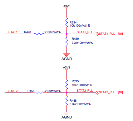
    Thanks for the update here. I'm actually surprised that the issue was with the PDN pin since there's a 10k pullup resistor populated, so this pin should have been pulled high to bring the device out of reset. But if this net was connected to some other source that was pulling it low (ex: GPIO from your host FPGA / microcontroller) then that would explain the issues you were seeing with programming the device. 

    If this solves your issue I'll go ahead and mark this thread as resolved.