This thread has been locked.

If you have a related question, please click the "Ask a related question" button in the top right corner. The newly created question will be automatically linked to this question.

LMX2571 lock detection time

Expert 3020 points
Other Parts Discussed in Thread: LMX2571, LMX2571EVM, CODELOADER

Hi team,


My customer is asking about lock detection time.

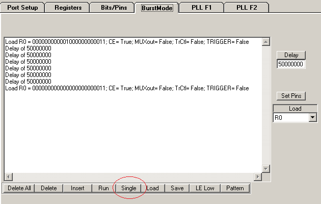
They measured the lock time at MUXout pin.

When CE pin goes down between 1,700ms, the lock time is needed 75ms after CE pin goes high.

However, RF output is stabled output frequency after 0.5ms from CE pin goes high.

There are too difference time between output stable and MUXout pin.

Could you please explain why the differ has been caused?

and if you have any idea to reduce the time of MUXout pin, please let me know.


Best Regards,

Yuki


  • Yuki,

    I am not sure if I fully understand the question.  If the CE pin goes from low to high and it takes 0.5 ms for the lock detect pin to indicate lock, this sounds about what I would expect.   It does depend somewhat on the loop bandwidth, but 500 us is a very typical time it  takes for the synthesizer to lock.   The LMX2571 does have many aids to speed up lock time, but if you power down the device then the voltage to the loop filter will drift and then the device needs to re-acquire lock.


    Regards,

    Dean

  • Hello Banerjee-san

    This question is our customers.

    When CE pin goes down long time,the lock time is long.
    Details is below.

    a, Power Down time : 1700msec ---> Lock Detection time : 75msec
    b, Power Down time : 1400msec ---> Lock Detection time : 65msec
    c, Power Down time : 1100msec ---> Lock Detection time : 50msec
    d, Power Down time : 900msec ---> Lock Detection time : 35msec
    d, Power Down time : 550msec ---> Lock Detection time : 0.5msec

    Why does the Lock Detection time become long as the Power Down time is longer?
    Is this the specification of LMX2571?

    If you have any idea to reduce the time of MUXout pin, please let me know.

    Best Regards,
  • Looking at these times, this looks like some capacitor is discharging while the device is powered down. This could be the loop filter capacitors, but I think it is more likely to be some LDO capacitor. If so, then reducing these capacitors might improve he lock time. These capacitors might be at the power supply pins. If it is easy to make these measurements, a crude but simple experiment is to place your finger on various power supply capacitors on the board while powered down and see which ones impact the lock detection time. The theory would be that you would be increasing the leakage to see which LDOs this is sensitive to.
  • Hello Banerjee-san,

    Thanks for your quick response.

    Now,when the Power Down is longer,the Lock up time is less than 1msec.
    But only the Lock Detect time is longer.

    And then,our customer used LMX2571EVM.
    So, the capacitance of the capacitor is I seem to be correct.

    Can you check the phenomenon using EVM?

    Best regards,

    Ito

  • Hello Dean-san,

    Could you please send your confirmation with using EVM?

    The customer wants to reject the phenomenon.

    Any your comments will be appreciated for the customer.


    Best Regards,

    Yuki


  • Yuki,


    I measured this time to be a few 100 us -- much faster than what you are seeing.

    However, this is if I was programming the R0 register another time.  When I only programmed the R0 register one time (this has the POWERDOWN bit in it), then I saw long and inconsistent lock times.

    See this exerpt from the datasheet:  

    The LMX2571 can be powered up and down using the CE pin or the POWERDOWN bit. All registers are preserved in memory while it is powered down. When the device comes out of the powered down state, either by resuming the POWERDOWN bit to zero or by pulling back CE pin HIGH (if it was powered down by CE pin), it is required that register R0 with FCAL_EN=1 be programmed again to re-calibrate the device.

    So if you are clicking the powerdown bit on CodeLoader on and off and seeing long times, the problem is likely that you are only programming the R0 register once.  In codeLoader, you can use the burst mode to do these experiments.


    Regards,
    Dean

  • Dear Dean

    Mr. Ito is holiday today, I send you to the message by deputy.

    ---His message---

    I've summarized this phenomenon in the documentation.
    Please confirm the  accompanying document.

    Questions are as follows.

     1. Why does the Lock Detection time become longer as the Power Down time is longer?

       [The actual lock time(output frequency) is less than 1msec.]

     2. Is it possible to reduce the lock detection time to the actual lock time ?

        [The customer wants to reduce the lock detection time for battery power saving.]

     3.What is the cause the difference between the Lock Detection time and power down time ?

            (1) circuit , for example capacitance value.

            (2) response time of lock detection circuit in the LMX2571.

            (3) other reason

    Best regards,

    Shinichi

    LMX2571 Lock Detection time.pptx

  • Hi Shinichi,

    First of all, make sure that you program R0 after CE is resumed to HIGH. This is required to re-calibrate the device after powerdown. The following illustrates the timing sequence after powerdown is resumed.

    CE goes HIGH -- wait time --> Program R0 -- response time --> MUXout becomes HIGH

    Total MUXout delay time after CE is HIGH = wait time + programming time + response time

    Wait time = 100us typical

    Programming time = depends on your system. For example, if the CLK rate is 1MHz, programming time = 24us.

    Response time = 76us typical

    here is the waveform. Green = CE, Blue = LE, Pink = MUXout

    Picture 1. CE goes HIGH, then program R0. After LE goes HIGH, MUXout becomes HIGH.

    Picture 2. this is the zoom of LE and MUXout traces.

  • Dear Noel

    Thank you for your reply.

    I confirm your comment and then feedback to the customer.

    I appreciate your great help.

    Best regards,

    Shinichi

  • Hello Noel

    Sorry, Corrections have been made.

    The customer didn't use CE pin.
    They use POWERDOWN bit with R0.
    By the way FCAL_EN is always 1.

    When it uses POWERDOWN bit,is your results different?

    Please tell me the notes of the case where the on / off using the POWERDOWN bit.

    Best regards,

    Manabu
  • Manabu,


    Just a few  things I wanted to make sure that were clear.

    1.     When I did my experiment I did above, I used the POWERDOWN bit, not the CE pin.

    2.     It not enough to simply have the FCAL_EN bit set to 1 all the time.    It may seem pointless to program a register that has already been programmed to the same value, but it is necessary because it is the action of programming the R0 register that is critical.

    Regards,

    Dean

  • Hello Dean-san

    Thanks for your quick response.

    By the way, when it is powered on does we must keep always the sequence([Recommended Initial Power on Programming Sequence],written in P15 of Datasheet) described in the data sheet?

    Or does the "Recommended Initial Power on Programming Sequence" to execute just only first time?

    Best regards,

    Manabu.

  • Manabu,
    You do not have to do the entire programming sequence after every power down. However, you DO have to program register R0 with FCAL=1 after every time you power up (with the POWERDOWN bit or pin), even if it has been previously programmed.
    Regards,Dean
  • Hello Dean-san

    Thank you for your quick reply.

    I confirm your comment and then feedback to the customer.

    I appreciate your great help.

    Best regards,

    Manabu

  • Hello Dean-san

    Our customers executed the following, but the phenomenon did not improve.

    --------------------------------------------------------
     1. Launch the LMX2571, And they multiplied by the lock.
         (Fpfd = 50.4MHz, Div = 10, 480MHz)

     2. POWERDOWN is performed (POWERDOWN = 1),
          at the same time to FCAL_EN = 0.
         (They sent the data[4098] to R0.)

     3. They waited a while. (more than 600mSec)

     4. And release the power down. (POWERDOWN = 0)
        At the same time, setting the FCAL_EN = 1.
        (They sent the data [3] to R0)
    ---------------------------------------------------------
    They executed above steps,but nothing has changed about it compared to before.
    Lock-up time is no change in the order of 1mSec.

    Please point out if there is a problem.

    Best regards,

    Manabu

  • Hi Manabu,

    Here is my test result with the following configuration:

    OSCin = 25.2MHz

    MULT = 2

    fpd = 50.4MHz

    VCO = 4800MHz

    Fout = 480MHz

    Program sequence:

    1. Power down - program R0 with FCAL_EN=0, POWERDOWN=1

    2. Power up - program R0 with FCAL_EN=0, POEWRDOWN=0

    3. Reload R0 - program R0 with FCAL_EN=1, POWERDOWN=0

    Green trace = LE in step 3. Blue trace = MUXout.

  • Hello Noel-san

    Thank you for always quick response.

    Our customer executed the same steps as yours, but the phenomenon did not improve.

    How long did you leave a interval between STEP1 and STEP2?
    If you left a interval less than 1sec,could you please execute as leave a intervals for more than 1sec between STEP1 and STEP2?

    ---------------------------------------------------------------------
    Step1. Power down - program R0 with FCAL_EN=0, POWERDOWN=1

    Step2. Power up - program R0 with FCAL_EN=0, POEWRDOWN=0
    ---------------------------------------------------------------------

    Best regards,

    Manabu
  • Hi Manabu,

    the time interval between step 1 and 2 was much more than 1s.
    could you send me their codeloader configuration file? in codeloader, click File --> Save.
  • Hello Noel-san

    We got customers configuration file.
    I attached configuration file.
    please check it.

    By the way,can you send me your config file?
    I'd like to recommend to execute your configuration file to the customer.

    Best regards,

    ManabuFile.zip

  • Hi Manabu,

    It seems that the customer is not using the latest codeloader, pls use the latest codeloader which is available to download from our website.

    Anyway, I think the problem is from the codeloader, there is some bugs here.

    in the following plots, green trace = LE, blue trace = MUXout.

    This plot shown, in the "Bits/Pins" tab, if you click POWERDOWN bit once (from 1 to 0), instead of programing the device once, codeloader actually program the device a couple of times. as we can see below, there are several LE pulses. From the last programming, you can see MUXout resume to HIGH. So if you measure the time when you click the button until MUXout is HIGH, you will get more than 70ms.

    We can use BurstMode to get away from the bug.

    in the "BurstMode" tab, we can create some specific sequences to program the device. For example,

    The first R0 is with POWERDOWN bit =1. Then I added a lot of delay between the second R0. The second R0 is with POWERDOWN=0. In the bottom, click the highlighted button until you get Single. After that, click the Run button, codeloader will program the device with the first R0, then Delay and then program the device with the second R0. That is, first powerdown and then resume powerdown.

    Here is the plot after you click the Run button. There are only two LE pulses, which is expected and correct. The time interval between powerdown and powerup is more than 1 second. 

    once it is powerup, MUXout goes up in about 200us.

    here is the configuration file with BurstMode script. Make sure you use the latest codeloader to restore this file.

    e2eB.zip

  • Hello Noel-san

    Our customer used the latest codeloader.
    But they couldn't improve the phenomenon.

    If you would like to confirm more information,please ask me.
    I'd like to try to get the more information from our customer.

    Best regards,

    Manabu