This thread has been locked.

If you have a related question, please click the "Ask a related question" button in the top right corner. The newly created question will be automatically linked to this question.

LMK04828 strict synchronization

Other Parts Discussed in Thread: LMK04828, LMK04821, CODELOADER

Hi e2e-ers,

I'm designing a JESD204B synthesis/acquisition system, and trying to synchronize JESD204B DACs and ADCs across different converters and across multiple boards. This seems to be a common question -- here are related links to show I've done some homework:

We're still finding the LMK04828 datasheet tough to parse precisely.

Our board-to-board clock distribution starts with a slow clock (~10 MHz) and an accompanying (synchronous) sync pulse. This clock and sync signal are fanned out to multiple LMK04828s to drive clock and SYSREF signals on many JESD204B ADCs and DACs. Following the advice linked above, we're planning on using the LMKs in Cascaded 0-Delay mode.

Is it possible to ensure the ADCs/DACs receive SYSREF pulses on the same O(1 GHz) clock edge in this scenario?

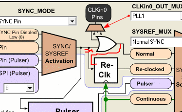
There are some hints in the datasheet (9.3.2.1.1: Setup of SYSREF Example), where SYNC is applied in two different configurations:

  1. The first SYNC pulse resets internal dividers within the LMK04828. This pulse needs to be consistent between LMK04828s. How can we configure two LMKs to accept this SYNC pulse synchronous to their input clocks? (If not, is there some other way to get consistent divider resets?)
  2. The second SYNC pulse triggers the pulser to reset downstream JESD204B devices. Can you confirm that this SYNC is synchronous to CLKinX when in Cascaded 0-delay mode? (If not, is there some other way to get consistent SYSREF pulses?)

Finally, when SYNC is used synchronously to an input clock, it has some setup/hold requirements -- and there are none in the datasheet. Any suggestions?

That's a bunch of questions jammed into a short amount of text -- thanks in advance for responding.

best,

Graeme

  • If you LMK0482x setup for pulser mode and raise SYNC pin 6 coherently with respect to the 10 MHz signal, somewhere in the middle to maximize setup/hold (you're correct - I don't have the data on this), I expect yes, you will achieve SYNC at the same 1 GHz clock edge.  Note there will always be some analog skew between each device due to phase detector phase error variation.  However digitally yes.  I expect the analog variation to also be less than 1 cycle of 1 GHz.

    So re-capping the details:

    Graeme Smecher said:
    The first SYNC pulse resets internal dividers within the LMK04828. This pulse needs to be consistent between LMK04828s. How can we configure two LMKs to accept this SYNC pulse synchronous to their input clocks? (If not, is there some other way to get consistent divider resets?)

    This first SYNC signal only aligns the dividers of each individual LMK04828.  The dividers will align by way of closed loop 0-delay between different LMK04828s.  This is why it is important that the low frequency being distributed to the reference be the GCD (greatest common divisor) of all output frequencies requiring deterministic phase.

    Graeme Smecher said:
    The second SYNC pulse triggers the pulser to reset downstream JESD204B devices. Can you confirm that this SYNC is synchronous to CLKinX when in Cascaded 0-delay mode? (If not, is there some other way to get consistent SYSREF pulses?)

    The downstream JESD204B devices being the converters and logic devices.

    Provided that the SYSREF frequency is the GCD frequency above, then requesting SYSREF pulser at any time for any devices ensures alignment for JESD204B purposes because the local multiframe clocks will be aligned.  The reason the LMFC is aligned is because the SYSREF period = n*LMFC period where n = 1, 2, 3, ... by JESD204B.  If it alignment happens a multiframe earlier or later it is ok because all JESD204B time is all modulus the local multiframe clock.

    Agreed?  In the case of your system being aligned at different times, for example all devices get SYSREF at the same instant but one which occurs one SYSREF cycle later... the LMFCs are synchronous and deterministic, but the SYSTEM will be invalid for 1 SYSREF cycle until the other device comes online.

    Now, it's possible I'm just plan wrong or your application has some additional requirements beyond what is supported in JESD204B (determinism modulus LMFC).  If you do want to ensure the SYSREF signals get sent to all converters/logic devices at the same deterministic instant, and not any of this determinism modulus SYSREF or LMFC frequency then, yes -- it is important to get the SYNC(SYSREF request / pulser start / etc) signal to all the LMK0482x devices in the same SYSREF period so that the SYNC/SYSREF signal occurs at the same instant in time across the entire system.  Which as you mention...

    Graeme Smecher said:
    Finally, when SYNC is used synchronously to an input clock, it has some setup/hold requirements -- and there are none in the datasheet. Any suggestions?

    I don't have answers for you at this time.  Part of the reason for this is the presupposition that in JESD204B world determinism is modulus LFMC, which is modulus SYSREF frequency.  However 10 MHz is quite slow, 100 ns should give quite a margin for a CMOS SYNC signal.

    ----

    I do want to put a second option out on the table for you, as it may simply your design.  See image below.  It does run into some of the same questions of setup and hold time though, however I have a quick answer for you below...

    Provided you have clean signals, you don't really need jitter cleaning from a VCXO or frequency multiplication of PLL1 to give PLL2 a nice high phase detector frequency to operate with...  In this case you can configure the device to operate in 0-delay PLL2 mode with the SYSREF divider taking the place of PLL N.  This will ensure that all the SYSREF dividers are aligned by 0-delay.  Then you can use the D flip flop clocked by the SYSREF divider output to re-sync an external signal.

    Now you can see with SYSREF_MUX = 1 (Re-clocked SYNC mode), the signal providing the re-clocking is going to share that same phase alignment between all the other LMK04828 devices within phase detector error.  This puts the burden on you to send a SYNC signal coherent to the phase detector frequency of PLL2 (meeting setup and hold times).

    I did a quick measurement on a system with a 122.88 MHz PDF (vs 100 MHz in illustration below) and found I could make adjustments from an upstream LMK04821 device (note LMK04828 shown in image below).  Using VCO1 = 2949.12 MHz and VCO div = 4 to increase the DDLY steps size to 1.35 ns per step on upstream LMK04821 I found that I could set DDLY step = 3, 4, 5, 6, 7, 8 of upstream LMK04821 device and keep the same phase relationship.  This suggest that given the 8.14 ns period of the phase detector/D flip flop re-clock that 6.75 ns span resulted in same position.  Hence the step+hold time is less than 1.39 ns.

    Note: key to use CLKin0 for SYNC/SYSREF input for improve setup/hold times.  This may not work with CMOS SYNC pin.  Also, CLKin0 is better to use as SYNC pin can cause some crosstalk onto VCOs of LMK0482x when toggling.

    In test I did:

    • Reference frequencies were 122.88 MHz, not 100 MHz.
    • Upstream device is LMK04821 with VCO1 = 2949.12 MHz and VCO_DIV = 4.
    • LMK04828 downstream PLL2 operated at 2949.12 MHz.

    If you chose to setup this, note the CodeLoader software has an error in the diagram on the SYSREF tab.  See correction in red below.  Point is CLKin0 can drive D ReClk FF input.

    73,

    Timothy

  • Hi Timothy,

    Thanks for such a detailed and prompt response. I'm sure we're not done asking questions -- but you've tackled these ones head-on, so I'm accepting the answer gratefully.

    cheers,
    Graeme (VE7CJG)
  • ...what made sense at 4 PM yesterday didn't at 4 AM today. I hope you don't mind clarifying a few details; let me know if you prefer to follow up as a separate posting.

    Timothy said:

    If you LMK0482x setup for pulser mode and raise SYNC pin 6 coherently with respect to the 10 MHz signal, somewhere in the middle to maximize setup/hold (you're correct - I don't have the data on this), I expect yes, you will achieve SYNC at the same 1 GHz clock edge.

    This is *exactly* what we're after. So, we've got two LMK04828s (perhaps on two separate boards). We feed each LMK04828 the same 10 MHz clock and source-synchronous SYNC signal.

    Timothy said:

    This first SYNC signal only aligns the dividers of each individual LMK04828.  The dividers will align by way of closed loop 0-delay between different LMK04828s.  This is why it is important that the low frequency being distributed to the reference be the GCD (greatest common divisor) of all output frequencies requiring deterministic phase.

    OK -- except the datasheet implies that SYNC is captured at the VCO clock domain (3 GHz).

    Specifically, I think the first SYNC pulse in 9.3.2.1.1 is problematic. The SYSREF divider on each LMK04828 is counting at ~3 GHz, and it must be reset (actually, released from reset) at the same time across all devices on the same fanout tier. (Otherwise, SYSREFs on different LMK04828s will be slightly misaligned.) If this is true, then SYNC's setup/hold constraints will be O(~100ps) -- a pretty tall order for a clock distribution network designed for 10 MHz. Are we misunderstanding the datasheet here? This would work if all our converters were attached to the same LMK04828, but as soon as we're synchronizing multiple LMK04828s, we're stuck.

    (Let's assume the first SYNC pulse worked. Then, the second SYNC triggers the pulser (or D flip-flop), which is clocked at the LMFC (125 MHz) via the SYSREF divider. These setup/hold requirements seem attainable, particularly since -- for JESD204B purposes -- it doesn't matter if the second SYNC occurs uniformly across all converters in the system.)

    Re-reading earlier e2e postings, I think my argument above is aligned with this one... in which case, I think I'm re-asking (and hopefully clarifying) Steven's question (4).

    thanks,

    Graeme

  • Graeme Smecher said:


    OK -- except the datasheet implies that SYNC is captured at the VCO clock domain (3 GHz).

    Specifically, I think the first SYNC pulse in 9.3.2.1.1 is problematic. The SYSREF divider on each LMK04828 is counting at ~3 GHz, and it must be reset (actually, released from reset) at the same time across all devices on the same fanout tier. (Otherwise, SYSREFs on different LMK04828s will be slightly misaligned.) If this is true, then SYNC's setup/hold constraints will be O(~100ps) -- a pretty tall order for a clock distribution network designed for 10 MHz. Are we misunderstanding the datasheet here? This would work if all our converters were attached to the same LMK04828, but as soon as we're synchronizing multiple LMK04828s, we're stuck.


    You are correct, the SYNC is captured at the VCO clock domain of 3 GHz for the 1st sync.  But it doesn't matter, because 0-delay will cause all the phases to shift and be aligned within tolerances of the analog phase delay error of the PLL.  As long as that low frequency information is the same across all devices, they will all phase the same phase and therefore future syncs will be aligned.

    • Think of JESD204B as open-loop 0-delay.  You have a SYSREF signal which marks a clock edge as reference.  Of course we know marking the same edge power-up to power-up it becomes more difficult at higher frequencies.  In the JESD204B system we measure/know what the error is between the two marked edges and therefore we can compensate for it.
    • Think of 0-delay as closed loop JESD204B.  The PLL takes any two edges from the reference divider and feedback divider and aligns them together.  The only error in the alignment is that of the analog phase detector, but think of it as a delay of 0 between the two signals.

    So even if initially the SYNC was on different 3 GHz VCO edges, the low frequency will align.  they occur any different 3 GHz clocks.  The phases will shift to align as part of locking and then the will share 3 GHz clock edges.

    So the question becomes, what are the requirements to assure 0-delay has deterministic alignment.  The simplest thing is to have the reference frequency = SYSREF frequency.  I have a feeling you don't have this now.... you mentioned that you had a 125 MHz LCM and a 10 MHz reference.  This tells me you are going to have 2 different phases possibilities (not deterministic like you want) because the GCD(10 MHz, 125 MHz) = 5 MHz.  So your reference frequency should be 5 MHz.

    Now if you do have the SYSREF output frequency at 125 MHz (SYSREF_DIV = 24 assuming 3000 MHz VCO) and a reference frequency at 10 MHz.  You could still work with this by way of the second method I mentioned (with the picture) in my last post.  Basically though you can't be careless about when you SYNC and count on the SYNC coming up at the right time later on.  Your window is not going to be the full 10 MHz (100 ns), rather it's going to be 8 ns relating to the SYSREF frequency of 125 MHz.  And for this, I expect you'd better use the CLKin0 for your SYNC input vs. the CMOS SYNC.

    Graeme Smecher said:
    for JESD204B purposes -- it doesn't matter if the second SYNC occurs uniformly across all converters in the system.

    Thanks for confirming my thought.

    73,

    Timothy

  • Hi Timothy,

    Thanks again for the thoughtful response. This is a complicated part, so let me walk through what I think you're suggesting. Hopefully you can confirm.

    For sake of argument, let's assume we distribute 5 MHz (instead of 10 MHz) so that the LMFC (125 MHz) divides evenly into the source clock. Then we follow the script in 9.3.2.1.1, and imagine the results across two parallel LMK04828s:

    1. The first SYNC pulse resets both parts' SYSREF dividers. Let's imagine it happens unevenly (one LMK04828's SYNC arrives slightly later than the other, so its SYSREF counter is 1 count behind.)
    2. Both LMKs' PLL2 feedback muxes (FBMux) are set to SYSREF (2). This causes the two LMKs to correct for the uneven count in (1).

    We now have both LMK04828s in alignment; their outputs aren't quite aligned, because the SYNC distribution wasn't even, but at least it's repeatable.

    Have I assumed correctly? I hadn't realized the SYSREF divider needed to be in the PLL2 feedback path. If so, I'm still not certain how much different two boards' SYNC pulses can be before we run into problems -- which may be why it's tricky to specify setup/hold for SYNC.

    best,

    Graeme