This thread has been locked.

If you have a related question, please click the "Ask a related question" button in the top right corner. The newly created question will be automatically linked to this question.

WEBENCH® Tools/NE555: The precision of oscillator issue

Part Number: NE555
Other Parts Discussed in Thread: CD4020B,

Tool/software: WEBENCH® Design Tools

Dear,

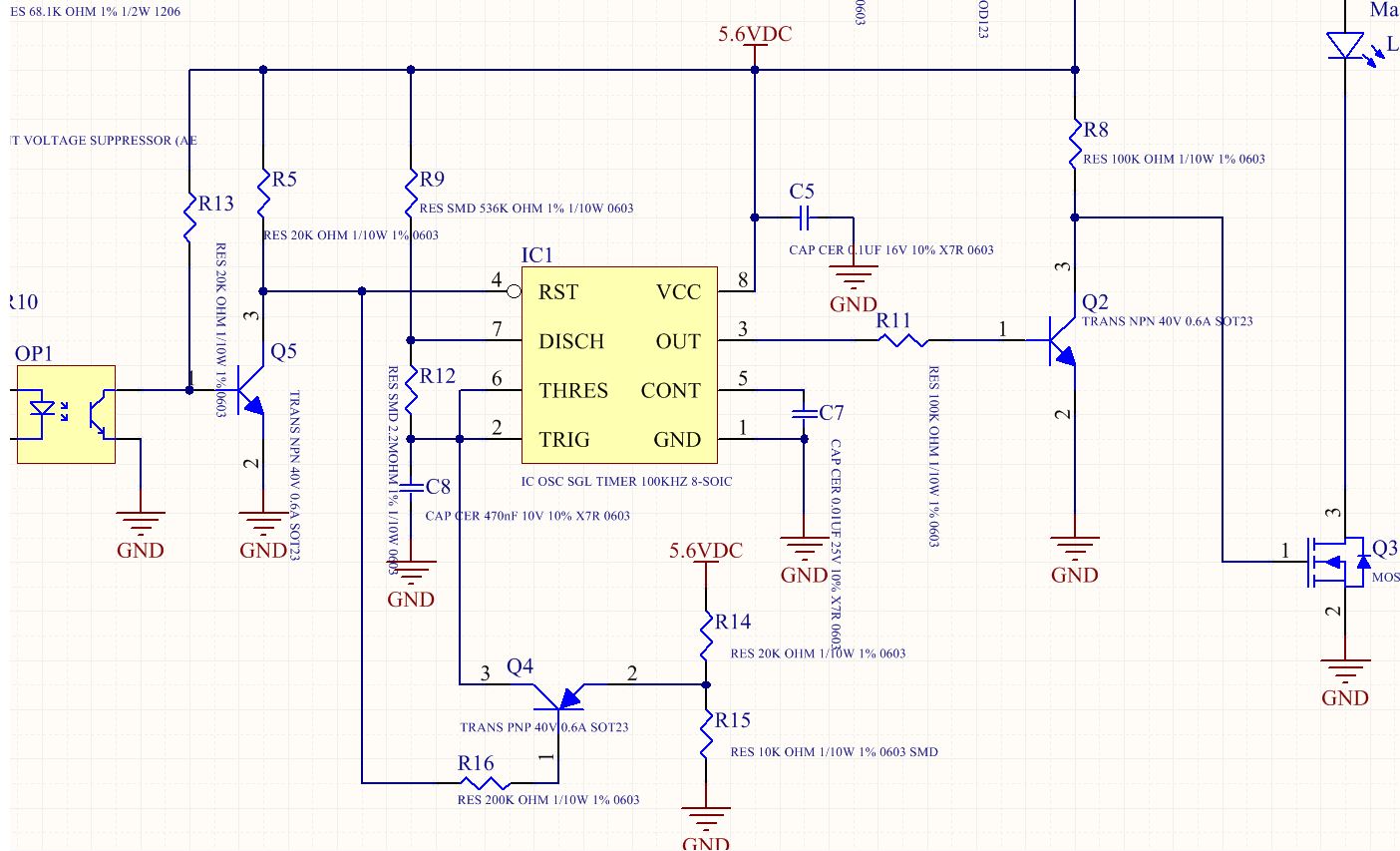
I built the board (PCBA) as the picture below to control the LED blinking at 0.62Hz

The output frequency measured on PCBA is 0.565Hz when starting Oscillating, and the frequency goes up to 0.574Hz after working 10minutes and continues goes up to 0.585 after working 30minutes( measured on 3 PCBAs).

Is the capacitor (C8) heating up and make the capacitance goes down, so the frequency goes up according?
Is the precision of output impacted by the tolerance of C8, R9, R11 mainly or have or other things? are there have any ways to improve the precision of frequency output?

And how about if I use a big resistance for R9 and R11? is the frequency will be an easy impact by the noise of the environment? (since I'd like to use a small capacitor (C8), It help to get the capacitor with 5%tolerace). 

Thanks,

Phuoc

  • Hello Phuoc,

    I see that a 1% frequency change is concerning. I suggest using a NPO/GOG capacitor type for better resistance to temperature, voltage, and aging.

    Here is some GOG/NPO data

    https://www.vishay.com/docs/45133/cognpodi.pdf

    Here is some NPO and X7R aging data

    https://www.digikey.com/en/articles/techzone/2016/jun/what-is-the-capacitance-of-this-capacitor

    A internet search for images with using this text, "7XR capacitor temperature coefficient chart" , shows poor X7R performance.  

    For "noise on the supply line", higher frequency noise on the supply voltage is not much of a problem as the C7 capacitor will filter that and it will average out on the charging current from R9. For EMI reception, try to keep R12, C8, Q4E close to pins 2 and 6 as possible. 

    Were you considering a lower value for C8?

  • Hello Ronald,

    Yes, I we're considering to use a small value of C8, so will have more chances get a NPO capacitor.

    But main concern is if use small value of C8, so the current through Oscillator circuit (R9,R11,C8) is too small then maybe it capture some noise in environment, is it?

    Thanks,

    Phuoc

  • Phuoc,

    I did a quick search and found that 470nF NPO caps are rare and expensive. However, for just 11 cents (1ku web price) you could add a 14 stage ripple counter (with reset) CD4020B that could reduce the capacitor * resistor value by 2^14 (16,384:1). With that, both the capacitor and resistors can be reduced for a much lower capacitor cost and more tolerance against noise and board leakages. This change should also greatly reduce output period jitter because the timer pulse period is "averaged".  

    Using the CD4020B Q14 output, the timer should run 16,384 times faster which is about 9257 Hz. At this speed, propagation delay in the NE555 will start to be a factor for variance. Therefore I suggest using the Q12 output instead. With Q12 output the timer should run 4,096 times faster which is about 2314 Hz.

    For the best support for CD4020B questions , start new thread with that part number.

  • Hi Ron,

    I do not have much space on board, so I prefer to use a capacitor X7R 470nF (I can accept some weakness of this capacitor).

    But I just want to know with 470nF and current set up as the previous picture, is the output easy impact by the noise capture from the environment?

  • Phuoc,

    C7 and C8 in addition to ground pin control the internal timing comparators. Well placed capacitors and good tracework should keep a lot noise out of the NE555 timing interval. The key is to keep noise from prematurely toggling the timing capacitors, C7 and C8 should be good at that. Most of the noise during the charge/discharge interval will average out. 

    However no circuit is immune if the noise source is powerful enough.