Because of the Thanksgiving holiday in the U.S., TI E2E™ design support forum responses may be delayed from November 25 through December 2. Thank you for your patience.

This thread has been locked.

If you have a related question, please click the "Ask a related question" button in the top right corner. The newly created question will be automatically linked to this question.

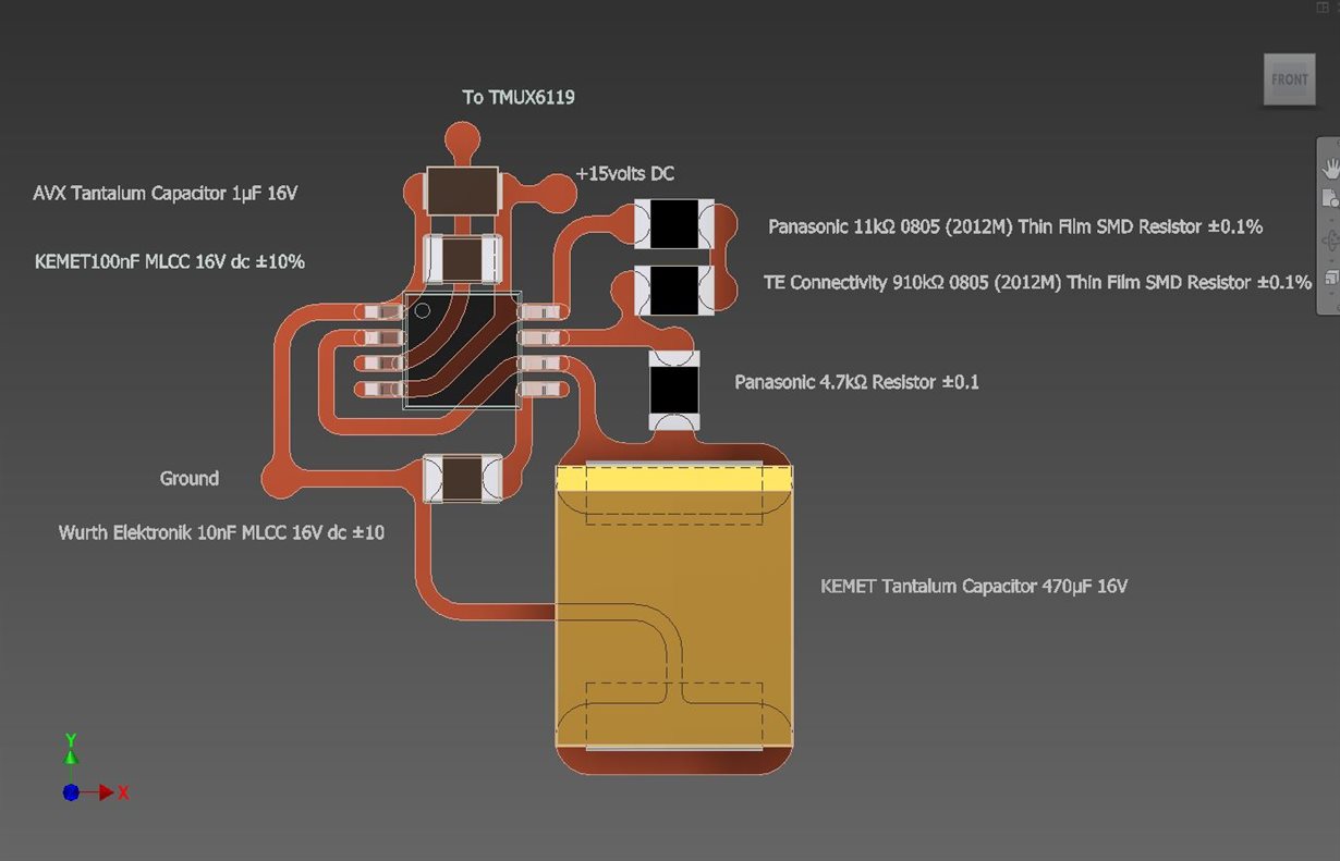
LM555: My previous layout was badly configured

Part Number: LM555
Other Parts Discussed in Thread: TMUX6119,

Ronald Michallick very kindly provided analysis and the following information regarding a part of my circuit involving a LM555 timer provided a high and low frequency pulse to a TMUX6119 switch.

As my pervious circuit was so badly wrong, would someone be so kind as to check that this circuit appended below,  is correctly configured please?

Thank you so much.

Christopher J James


Christopher,

No interconnects needed. Just connect pin 3 to the select pin on the analogue switch IC. Ground goes to ground. VCC+ can use same positive supply that the analogue switch uses. 

The data sheet suggests adding bypass capacitance to power pin (+15V)

0.1 uF bypass ceramic capacitor
1 uF electrolytic bypass capacitor

Using equations in the data sheet , here are the results.

The TMUX needs a VIL less than 0.8V , the LM555 can meet that need.

The TMUX needs a VIH greater than 2V, the LM555 can meet that need.

I have said this multiples times, but I will say it again. LM555 pin 3 can connect to the TMUX directly without any other components. 

LM555 low output will be near 0V. This level is valid (less than 0.8V). LM555 high output will be roughly 14V. This level is valid (greater than 2V, but less than or equal to VCC, 15V).

Regards,
Ronald Michallick

  • Christopher,

    The new board layout looks proper. However I do not know about the manufacturability of curved tacess.

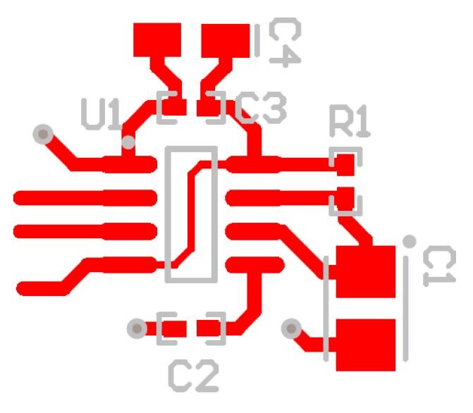
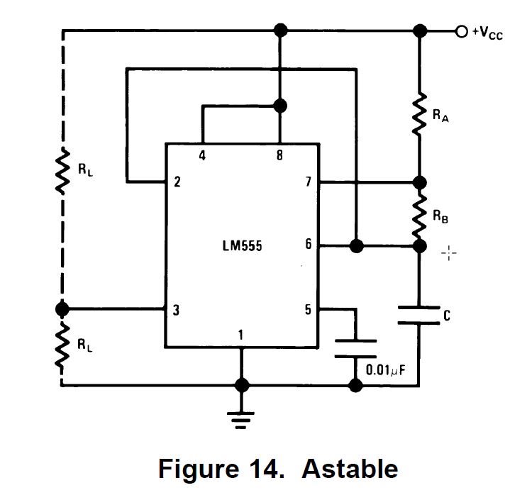
    This layout is for mono-stable only so it won't work for your application.

    Start a new thread with TMUX6119 as the part number and ask them if LM555 output is good for select pin. 

    Someone else will answer. Almost all questions with LM555 (as the part number) will be answered just by me.

  • Dear Roland,

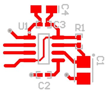
    I am well aware that the footprint was incorrect, but your previous advice seemed to draw reference to C3 and C4 on the power input Pin8. which is why I included it.

    But you have confounded me about having to now check it with another thread, for it was my understanding that you had already kindly run an analysis, and provided with me with the values of capacitors and resistors to use?

    Christopher

    PS The layout is unique to us as an organisation. In time as our work is made public, you will understand the need for our method. In short, we are not just interested in the flow of electricity, but in the flow of Bioenergy and thus our circuits are designed more akin to how nature would have them.

  • Christopher,

    Yes, there seems to be a disconnect in communication. I will think this through and respond by Thursday Wednesday.

  • Dear Ronald,

    I would be most grateful thank you.

    Christopher

  • Christopher,

    I studied all four of the the relevant e2e threads. Summary is below.

    I posted a solution within 24 hours. Then we had many posts about the output loading, so I assumed there were still some doubts about the interconnection between LM555 and TMUX. Your newer posts referenced me, therefore I believed that you were looking for a second opinion. Using LM555 as a part number will almost always reach me. A second opinion really needs to come from a second person. The best 'second person' would be one who regularly supports the TXUX. That is why I suggest opening the TMUX post. I am glad that you did and I see that went well.

  • Dear Ronald,


    I believe it is just that I do not understand the format in which you work and thus do not recognise, and hence abide, by the nuances which you take for granted.


    Imagine that I was a Martian and when you reached out to shake my hand, I thought that it was a gesture equivalent to punching me in the face. We both meant each other nothing but good grace, yet our misunderstanding caused the mismatch.


    I have nothing but the highest of respect for your kind guidance, without which, I would not be where I am with my design today.


    I am wondering if it is within your field of operation to advise me on a possible choice of an isolated gate switch, either single pole or double pole?


    I have 3.3 volts dc with which to drive the switch but need it to be capable of the isolated switching of 15 volts dc.


    Can you help, please?


    Once again I am most grateful, and hope that my reply clarifies any misunderstanding that there might have been?
    Yours truly,


    Christopher J James


    PS You queried the manufacturability of my curved designs? In the short term, we propose to use CNC silver-ink printing technology, that will even print on pliable curved membranes. But we do have to resolve how to overprint multiple circuits on resin spheres. This is more where my skills come into play, hence why I am such a novice when it comes to electronics. I developed CNC machinery and modelling when they first came to the forefront in the late seventies and early eighties.

  • Christopher,

    Sorry, I don't have a switch recommendation. 

  • Dear Ronald,

    Thank you, nevertheless.

    Christopher