Part Number: LMX2594EVM
Other Parts Discussed in Thread: LMX2594, , LMX2572EVM
Hi Dean,
I noticed that you mentioned the need for OSCin as the trigger channel. I use a single channel to monitor the phase change (oscilloscope model DPO4104). I have not observed phase shift. Is it necessary to use dual channels? Is this critical?
All my steps are as follows, can you find where I made a mistake?
Use TICS Pro to phase shift the LMX2594.
1) Connect the control board and LMX2594EVM
2) 3.3V Vcc power on
3) Open TICS Pro
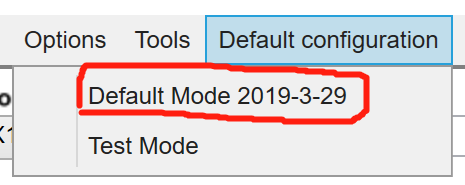
4) Load default mode, output frequency 7000MHz
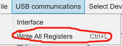
5) Write all registers
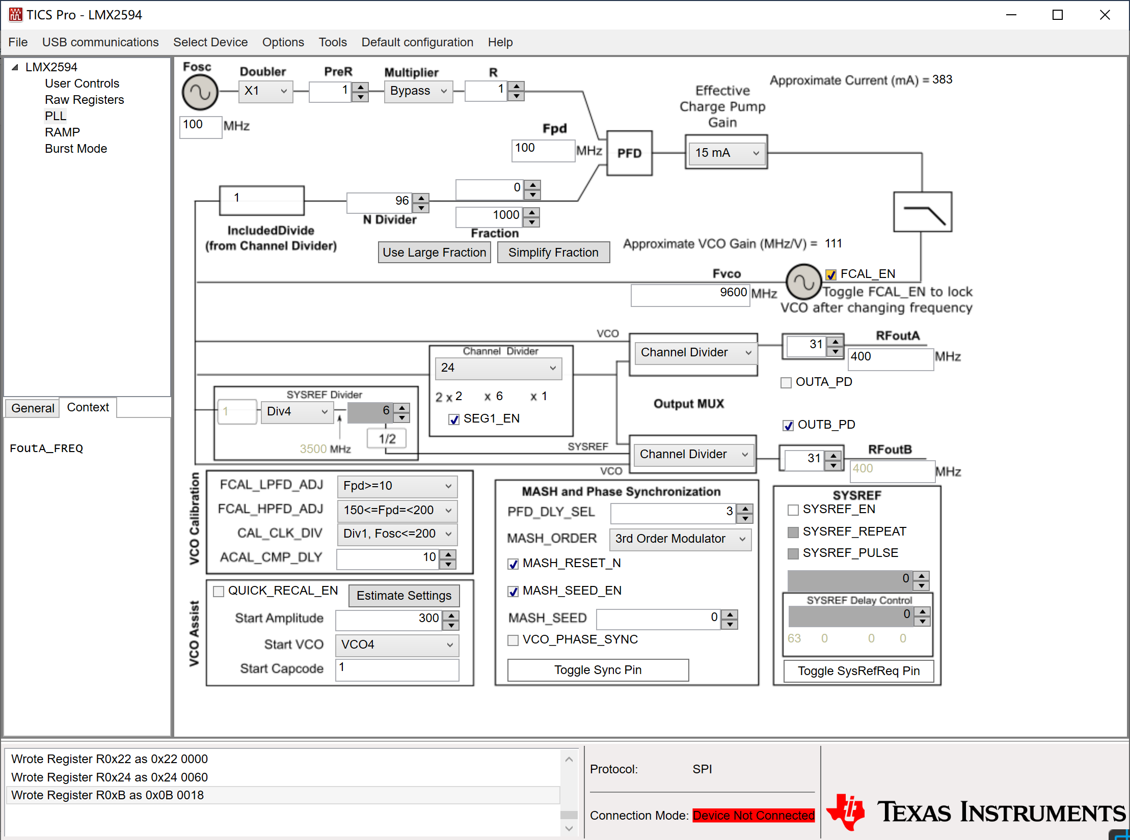
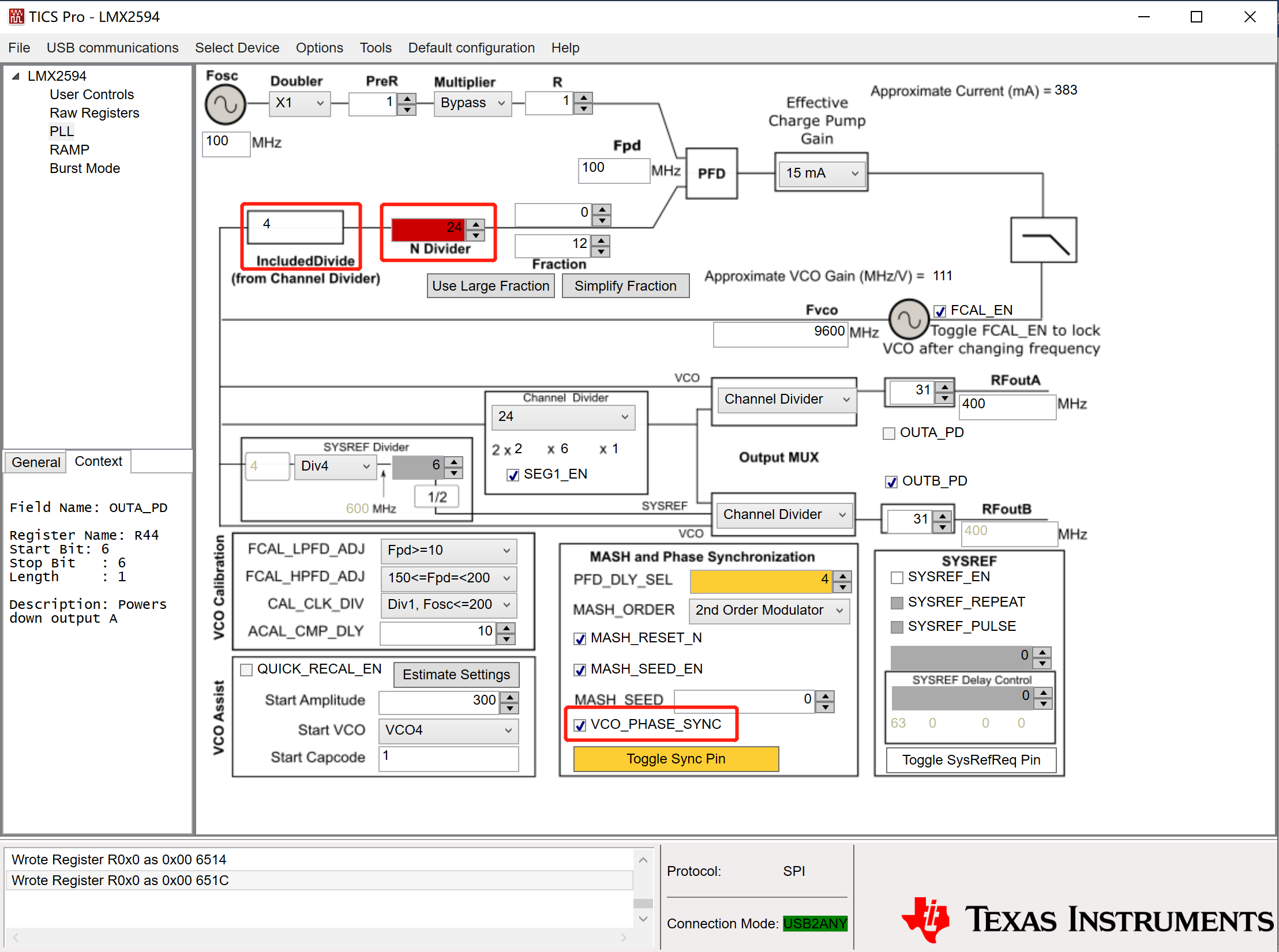
6) Change the output frequency to 400MHz,
Doubler=1,
R=1,
and MASH_SEED=1,
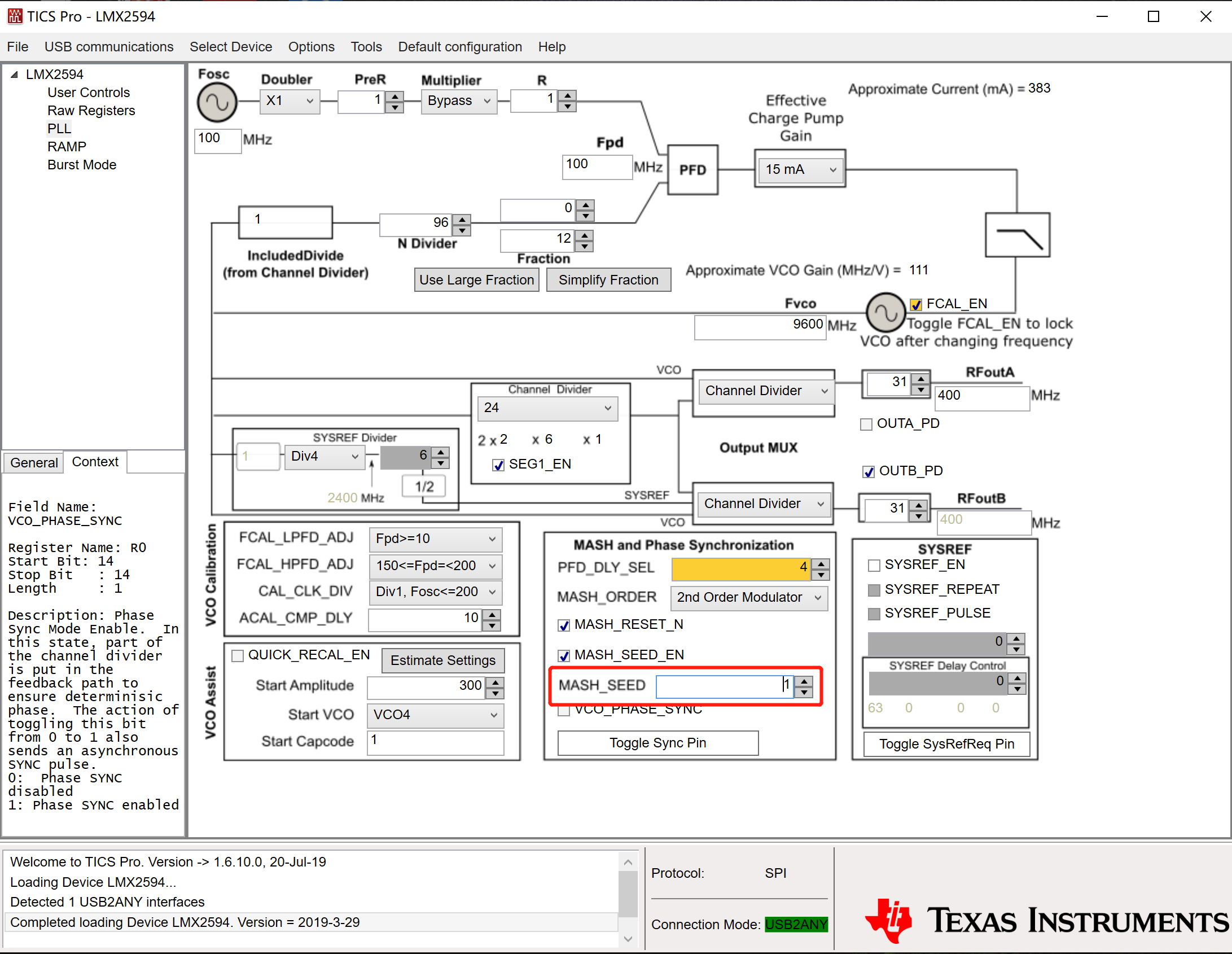
then Toggle FCAL_EN=1 as the following picture
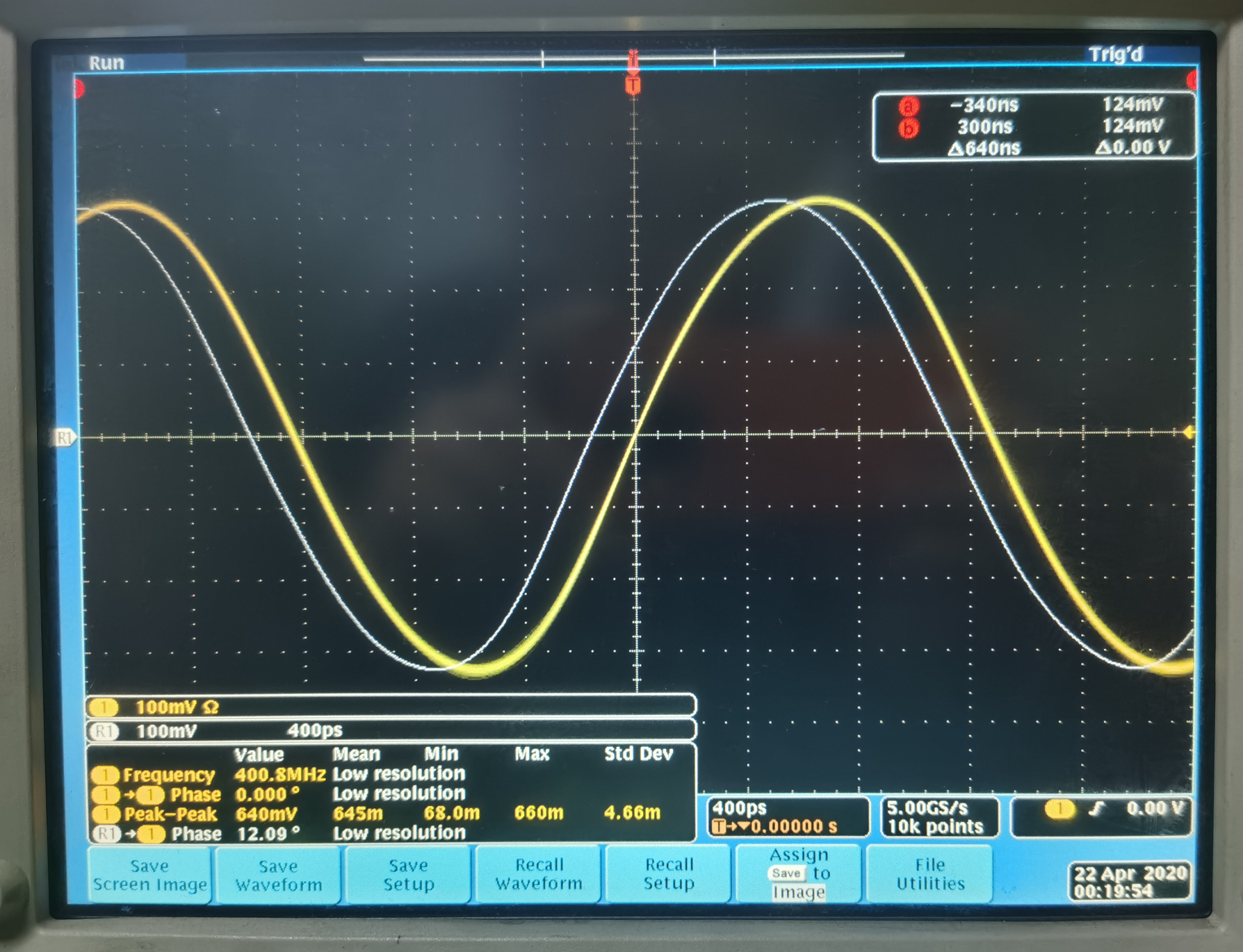
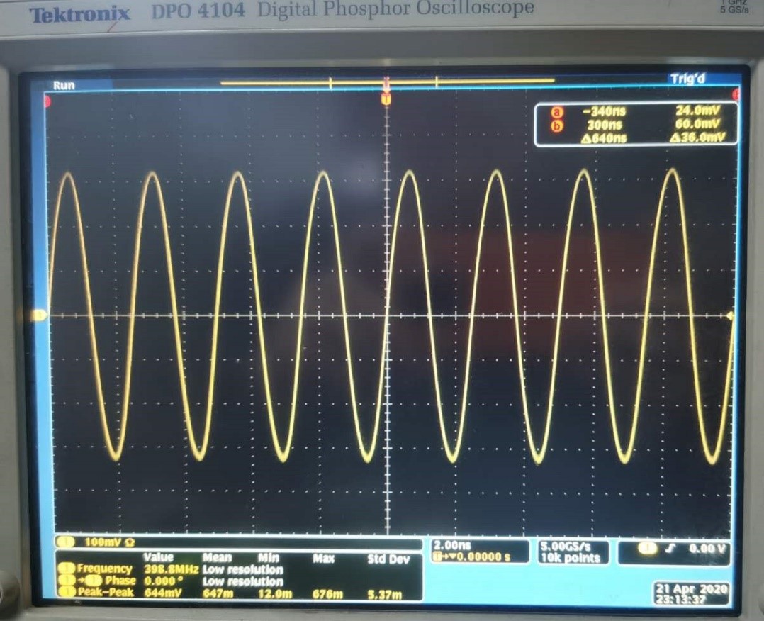
The waveform on the oscilloscope is as shown:
7) According to the description on page 29 of LMX2594 datasheet, 7.3.11, as follows
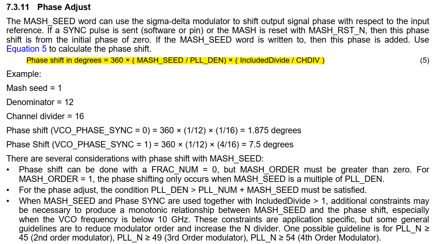
Value: MASH_SEED=1
PLL_DEN=12
CHDIV=16
IncludeDivide=1 (when VCO_PHASE_SYNC=0)
IncludeDivide=4 (when VCO_PHASE_SYNC=1)
At this time, the conditions are met:PLL_DEN(12)>PLL_NUM(0)+MASH_SEED(1)
Modify the parameters according to the above data,the first step change PLL_DEN from 1000 to 12,then press ENTER,The second step is to modify the value of CHDIV. When CHDIV is changed from 24 to 16, when I press Enter, the output frequency is automatically locked to 600MHz, as shown in the figure
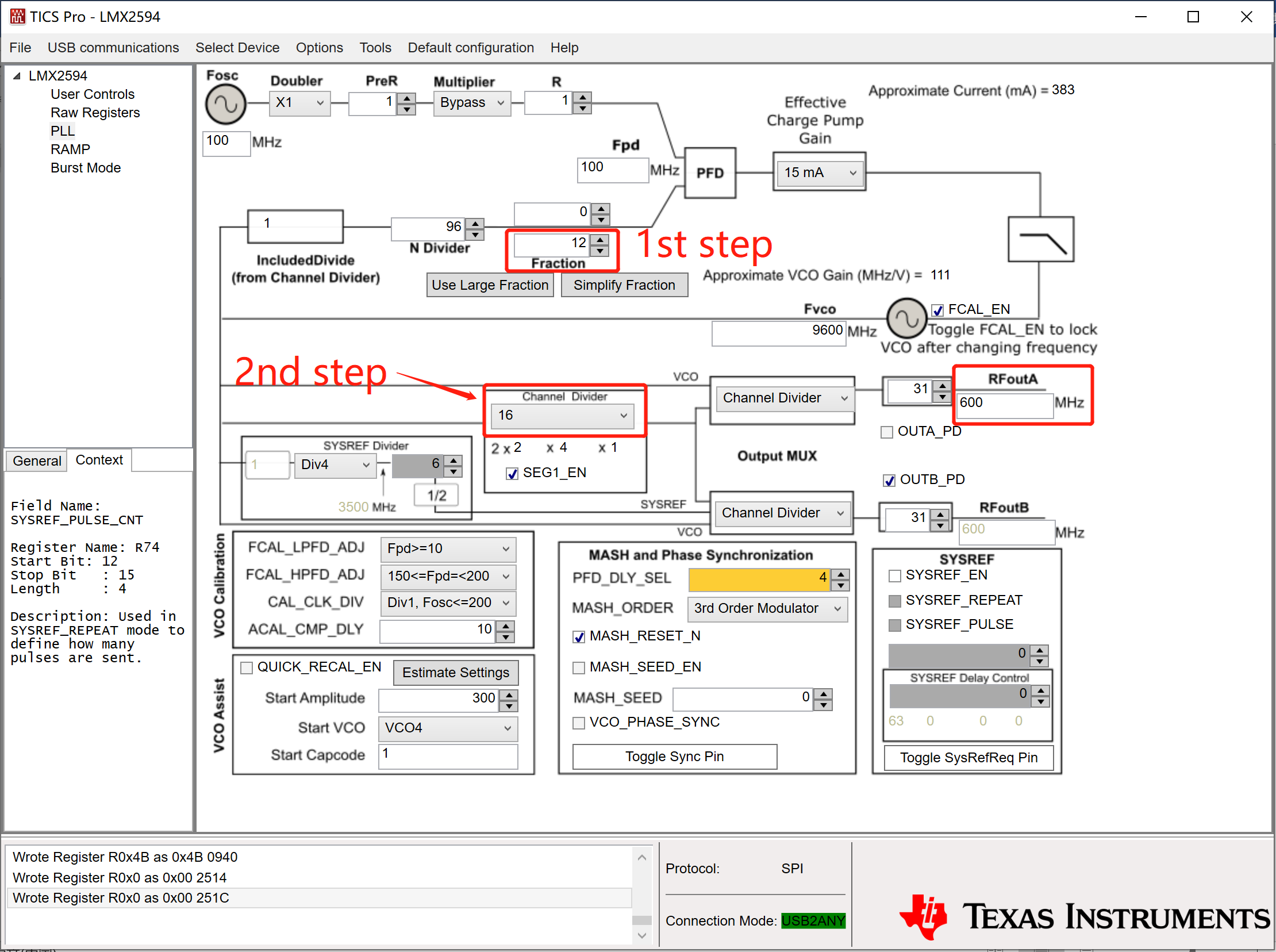
At this time, I found that when CHDIV is 16, no matter how to change the value of N Divide or Doubler or R, no matter whether VCO_PHASE_SYNC is equal to 1, LMX2594 cannot be locked at the 400MHz output frequency. For the output frequency to be 400MHz, CHDIV must be equal to 24.
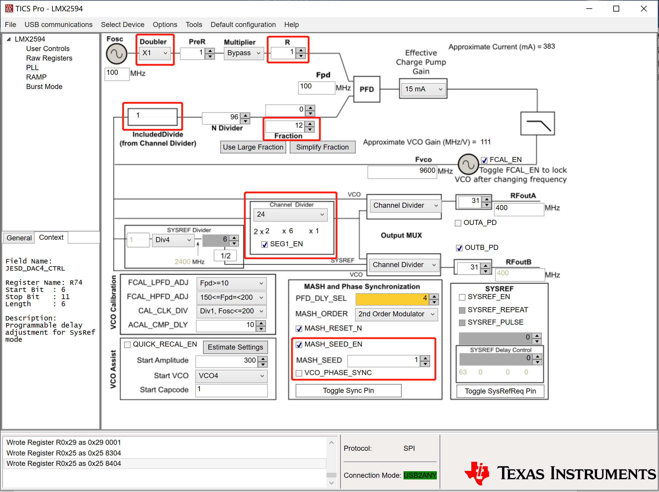
Next, modify the value to:
MASH_SEED=1
PLL_DEN=12
CHDIV=24
MASH_SEED_EN=1
I found that when VCO_PHASE_SYNC = 1, IncludeDivide will automatically become 4, N Divide will become 24, and the output signal will lose lock at this time, as shown in the figure
There can only be one set of valid values:
MASH_SEED=1
PLL_DEN=12
CHDIV=24
MASH_SEED_EN=1
VCO_PHASE_SYNC=0
To meet the conditions: PLL_DEN(12)>PLL_NUM(0)+MASH_SEED(1)
According to the formula : Phase shift in degrees = 360 × ( MASH_SEED / PLL_DEN) × ( IncludedDivide / CHDIV )
Can be calculated: Phase shift in degrees=360×(1/12)×(1/24)=1.25°
All parameters are set as shown below
Then, move the mouse into the box of MASH_SEED, the cursor flashes, and every time I press the Enter, the cursor continues to flash, but I still can't observe the phase shift. as the picture shows