A related question is a question created from another question. When the related question is created, it will be automatically linked to the original question.
If you have a related question, please click the "Ask a related question" button in the top right corner. The newly created question will be automatically linked to this question.
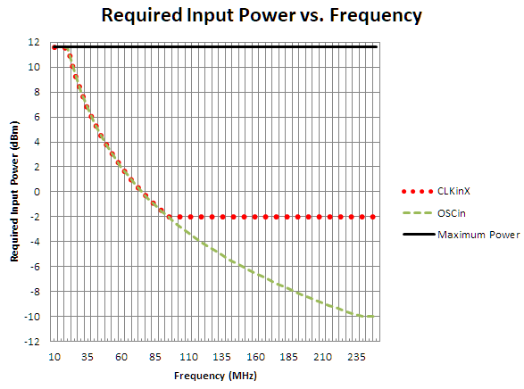
The CLKin and OSCin inputs can both be driven by a single-ended sinewave. Minimum input power requirement is determined by the minimum required slew rate, minimum single-ended swing, and the supply voltage limits. See the graph below which assumes 50Ω single-ended termination and AC-coupling. The input power should be above the lines for each input and should not exceed the listed maximum peak to peak voltage (2.4V, or 10+20log(2.4V/2) = 11.6dBm).
Question 1 : I am inputting 250 MHz to the LMK04832 and using this to output coherent frequencies at 750 MHz and 3 GHz.
The 3 GHz output from the LMK04832 will also be input to a LMX2615 to output a coherent 6 GHz clock.
Are you happy with all of the above?.
Question 2: 250 MHz, 750 MHz and 3000 MHz are all convenient multiples.
Given that the input to the LMK04832 is 250 MHz, can the LMK04832 generate output clocks which are NOT convenient multiples, e.g. 751.333 MHz or 3104 MHz?
If so, will the LMX2615 simply double its input frequency (approximately 3 GHz) to maintain coherency?
1. 250MHz is an acceptable phase detector frequency for PLL2, and 750MHz can be generated from VCO at 3GHz (divide-by-4). I think this would be satisfactory.
However, the LMX2615 has a maximum phase detector frequency of only 250MHz when used with an integer-N divider, and a maximum input frequency of 1GHz. So sending 3GHz to LMX2615 does not make sense. At most you could send 1GHz and divide the input by 4.
2. The LMK04832 has only integer output dividers (no fractional dividers), so it cannot generate fractions like 751.333 or 3104MHz and remain locked to a 250MHz input.
Again, the input frequency limitations on the LMX2615 render this question difficult to answer appropriately. Because the LMX2615 is a PLL, if you can somehow vary the input clock to the LMX2615 by some amount, the output frequency of the LMX2615 will change proportionally and will maintain phase coherency with the LMX2615 input clock, but not the 250MHz input to LMK04832. But in the scheme you proposed (LMK04832 driving LMX2615), this should never be possible, since all the dividers in the LMK04832 are integer dividers.
The LMX2615 contains an integer-N divider and an optional fractional-N component added to the integer divider; your requested output frequency does not require the optional fractional-N component. Since your output from LMK04832 is 750MHz, and would be reduced to 250MHz at the LMX2615 phase detector, the 6GHz from LMX2615 12GHz VCO could be integer divided by 48 to match the phase detector rate and integer divided by 2 to achieve the 6GHz output.
Since all the divides in your use case are integers, the phase of the 6GHz would be coherent with the 3GHz and 750MHz clocks from the LMK04832.
Can you also confirm that I can use the LMK04832 to generate either two 750 MHz or two 3 GHz clocks, with a coherent 270 degrees phase shift between each,
You can use the LMK04832 to generate two 750MHz clocks with a coherent 270° phase shift between each.
You cannot use the LMK04832 to generate two 3GHz clocks with a coherent 270° phase shift between each.
The reason is because device clock phase shift is controlled by delaying output clocks by some number of clock distribution path cycles. Since 3GHz is the clock distribution path frequency and the output frequency, it is not possible to delay the 3GHz output by 270°. However, since at 750MHz 270° phase shift is equivalent to three 3GHz clock distribution path cycles, phase shifting 750MHz by 270° is possible.
You can use the LMK04832 to generate two 3GHz clocks with a coherent 180° phase shift between each. Digital delay values can be clock distribution path half-cycles. They cannot be quarter-cycles as would be required for 270° phase shift.
LMK04832 VCO ranges are listed on the first page of the datasheet and in the electrical characteristics table as 2440 to 2580 MHz and 2945 to 3255 MHz. So you could not generate 2.9GHz on LMK04832 using the internal VCOs.
You could use an external VCO to generate 2.9GHz (maximum external VCO range is given in the datasheet electrical characteristics as up to 3250MHz). With 250MHz the phase detector frequency would be GCD(2900, 250) = 50MHz.
You still could not generate 2.9GHz + 270° phase shift, for the same reason you could not generate 270° phase shift at 3GHz: the clock distribution frequency is used to establish the digital phase delay on the device clocks.
Moreover, 750MHz is not an integer quotient of 2.9GHz. So using 2.9GHz VCO, the LMK04832 could not generate 750MHz.
In summary, you cannot generate 750 MHz, 750 MHz + 270°, 2.9 GHz and 2.9 GHz + 270° with a 250 MHz LVDS XO input to the LMK04832.
The maximum clock output frequency supported by the LMK04832 is equal to the clock distribution frequency, so up to 3250MHz in external VCO mode or 3255MHz in internal VCO mode.
With LMK04832 your request will not be possible, because LMK04832 cannot satisfy the 3GHz/3GHz + 270° requirement (with 3GHz, or with any close frequency).
On the other hand, the LMK04828 is P2P compatible with LMK04832, can generate 3GHz with the internal VCO frequency, and includes analog delay in the device clock path which could be used to generate the required phase offset between the 3GHz clocks. The LMK04828 device clock analog delay step size is approximately 25ns, and enabling the analog delay path inserts a fixed 500ps delay on the device clock. At 3GHz, one cycle is 333.33ps, and 270° is 3/4 * 333.33ps = 250ps. So, by enabling analog delay on both clocks, and setting the delay value of the clocks 250ps apart, you could achieve the 270° phase offset.
The LMK04828 can also divide down the 3GHz VCO frequency to 750MHz, and can use the digital delay to guarantee 270° phase offset on one of the clocks. Since the LMK04828 has seven output dividers, it should be able to support all five of the output clocks required in your application.
Note that the phase detector in the LMK04828 is rated only to 155MHz, so your phase detector frequency must be 125MHz.
In retrospect, I realize LMK04828 may not be an option for the application given the other part choices in the design. With a single LMK04832 it is not possible to generate the 3GHz + 270° all on-chip, but if you cascade one device into another, offset the phase of the second device input reference by 270° with respect to the first device 3GHz output, and use zero-delay mode on the second device to relate the input phase to the output phase, it should be possible to ensure 270° offset between the two 3GHz signals. Otherwise, I think the only other solutions that use a single LMK04832 involve some kind of discrete quadrature generator.
Since the least common multiple of 750MHz and 2500MHz is 7500MHz, and the highest clock distribution frequency can be no greater than 3255MHz (or 3250MHz if external) it is not possible for a single LMK04832 to generate both of these frequencies simultaneously.
As before, if you can use multiple devices, it should be possible to generate all of these outputs. However, you would need at least three PLLs: two to generate the 2500MHz and the 2500MHz + 270°, and a third to generate the 750MHz from a 3000MHz VCO. Again, by use of zero-delay, you could ensure the required input-to-output phase relationship across all three PLLs.
For frequency planning questions, it may help to download TICS Pro software, open the device profile for the LMK04832, and use the built-in frequency planner page to check if a frequency plan is possible. While it can't check for phase alignment, it could at least inform you if a given set of frequencies could be generated by a single device.
If you'd like to follow up offline I can accomodate that. I'll follow up with you via email to schedule a call.
As we discussed in our call, it is possible to generate 750MHz, 750MHz + 270°, 1.5GHz, 1.5GHz + 180°, and 1.5GHz + 270° on the same device, using a 3GHz VCO. This can be accomplished using the digital delay and half-step adjustments.
Since I offered to continue supporting you offline, I'll mark this thread as resolved for now. You are welcome to continue the E2E thread, or continue support offline, whichever is most convenient for you.