Hello ti expert
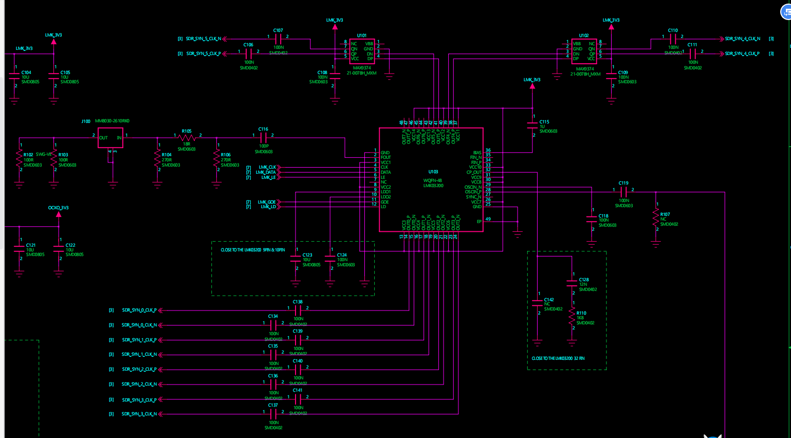
1: Based on lmk03200 Data Manual 6.2.1 0- delay mode example1,For each register configuration, clk0,clk1 output frequency parameters have been changing in debugging, and the waveform has been beating? What is the reason?
2:Frequency calibration flow chart, blue mark, valid oscin this effective how to know? This pin foot is directly connected to the reference frequency mhz,10
3:Could you send a 0 delay mode configuration flow chart?