This thread has been locked.

If you have a related question, please click the "Ask a related question" button in the top right corner. The newly created question will be automatically linked to this question.

LMX2595: Spurious issues

Part Number: LMX2595

With Reference to suggestions in the following thread

https://e2e.ti.com/support/clock-timing-group/clock-and-timing/f/clock-timing-forum/988413/lmx2595-spurious-at-50khz-offset/3662459#3662459

With the following, changes did not found any improvements,

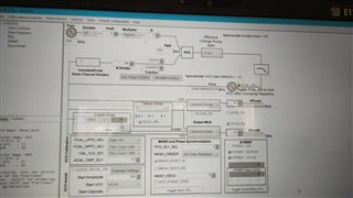
- make CAL_CLK_DIV = Div2.

- use a smaller charge pump current

- use third-order loop filter  (Loop filter schematic is attached for reference)

- set PLL_DEN to something like 2345678 instead of an integer multiple of 100

By varying the REF Input power level, testing carried out and observed spurious level change. Results are as follow,

Condtion:-

REF IP Level= -8dBm

Observation:

Spurious level = -44dBc

REF IP Level = +2dBm

Observation:

Spurious level = -53dBc

REF IP Level = +8dBm

Observation:

Spurious level = -61dBc

Setup for above testing

Please help me to solve this spurious issue. Our frequency band is 1.3 to 2.4GHz. Spurious is not seen for integer frequency. Spurious offset is changing as per set frequency so it is not from the power supply.

  • Hi Sushant,

    Can you try remove the filter in front of OSCin?

  • Hi Noel, As per suggestion i have removed filter in front of OSCin but not seen any improvements in the sectrum.

    Regards

    Sushant

  • Hi Sushant,

    The only factor that is related to the spurs vs OSCin input level is the slew rate of OSCin signal, higher slew rate tends to have smaller spurs.

    When you did the OSCin input level vs spurs test, were you using a signal generator?

    In your system board, what will be the clock source?

  • REF i am giving from the 100MHz OCXO (NI-100M-2900) and power level changing with attenuators. OCXO output is clean there is not spuriouses.

    Also i have observed that 2nd harmonic is coming only -6 dBc down but as per datasheet, it should be -20 to -30dBc.

    To see any effect of HPF + LPF combination in output line, We bypassed the HPF and checked the performance but no improvements.

  • Hi Sushant,

    you've got -6dBc harmonic even with the LPF there? That does not make sense. Is the 0.01µF decoupling capacitor at the junction of the two 50Ω pull-up resistor a broadband capacitor? Check the BOM of the EVM user's guide for the capacitor we used.

    I don't have a good guess on the spurs, maybe we should check the layout. How is the layout of the loop filter? Can you share the layout around synthesizer?

    Since OSCin can accept input voltage up to 2V, you can continue to use 8dBm. 

  • you've got -6dBc harmonic even with the LPF there? 

    -> When PLL output freq we are setting for 1300MHz, 2nd harmonic is 2600MHz. But it falls under the passband of LPF so the filter will not give rejection for lower frequency in our band of interest. But as per datasheet we are expecting -20 to -30dBc 2nd harmonic.

     Is the 0.01µF decoupling capacitor at the junction of the two 50Ω pull-up resistor a broadband capacitor?

    -> We have used same capacitor as per EVM "520L103KT16T"

    I don't have a good guess on the spurs, maybe we should check the layout. How is the layout of the loop filter? Can you share the layout around synthesizer?

    -> Please share me your mail ID.

  • Hi Sushant,

    I will shoot you a mail.

  • This issue is taken offline, let's close the post.