This thread has been locked.

If you have a related question, please click the "Ask a related question" button in the top right corner. The newly created question will be automatically linked to this question.

LMP90100: LMP90100 EXAMPLE CODE

Part Number: LMP90100
Other Parts Discussed in Thread: ADS124S08
Is there a sample code to program the LMP90100 with any processor other than the MSP430?
At the same time, can you share with me if there are sample codes for measuring and calculating the PT100 temperature from LMP90100?
  • Hi ASSA,

    As stated in previous posts, the only example code we have for the LMP90100 is for the MSP430.

    We do have temperature sensor example code here: https://www.ti.com/tool/ADC-TEMP-SENSOR-FW

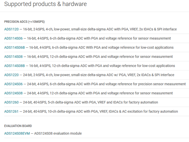
    The firmware supports the ADCs shown below, and unfortunately this list does not include the LMP90100. However, it might be possible to modify the code for your purposes if you would like.

    A better idea might be to move to a newer device, specifically the ADS124S08. This ADC is the next-next-generation version of the LMP90100, and is simpler to use. I am not aware of any PIC firmware available for the ADS124S08, but the temp sensor FW will be easily portable to another processor. Also, the ADS124S08 is a smaller ADC, has more input channels, offers lower noise, lower power, better DC performance, more features, and again is much simpler to use.

    -Bryan

  • I have a motherboard designed as I mentioned earlier unfortunately so I have to work with the lmp90100 ADC. I am trying to correct the situation in line with the advice you have given and the advice I have received from the processor forum page. But unfortunately I am not successful in this case. I've looked through all the product datasheets one by one and still don't understand what my problem is. Under normal conditions, I need to be able to complete the writing or reading process when I set the CS pin to the LOW position, send the address information and then the value information with SPI, and then activate the CS pin. But unfortunately that is the case with this product. Can you please help with this issue?

  • Hi ASSA,

    Again, I will stress that I do not have sufficient information to provide any more support on this topic. We really need to see logic analyzer data to make sure the timing requirements are being followed and that the correct information is being sent to the ADC.

    Are you able to read back registers, or get any sort of response from the ADC? Can you get DRDY to toggle after starting conversions?

    Is the ADC powered correctly? Do the supplies droop at all when a load is applied to the system? There is no way to know since a schematic has not been provided.

    Are there any mechanical issues with the board? Poor solder joints, solder blobs shorting pins together, etc.?

    Is the PIC setup correctly, specifically the SPI peripheral? Is the right SPI mode being used?

    -Bryan

  • The drawing file is attached with all the details. The solders seem to be in good condition.

    2.rar