This thread has been locked.

If you have a related question, please click the "Ask a related question" button in the top right corner. The newly created question will be automatically linked to this question.

ADS1298ECGFE-PDK: Unable to communicate via SPI

Part Number: ADS1298ECGFE-PDK
Other Parts Discussed in Thread: ADS1298,

Hi,

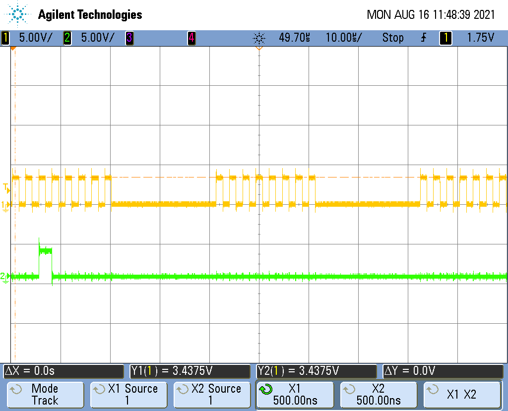
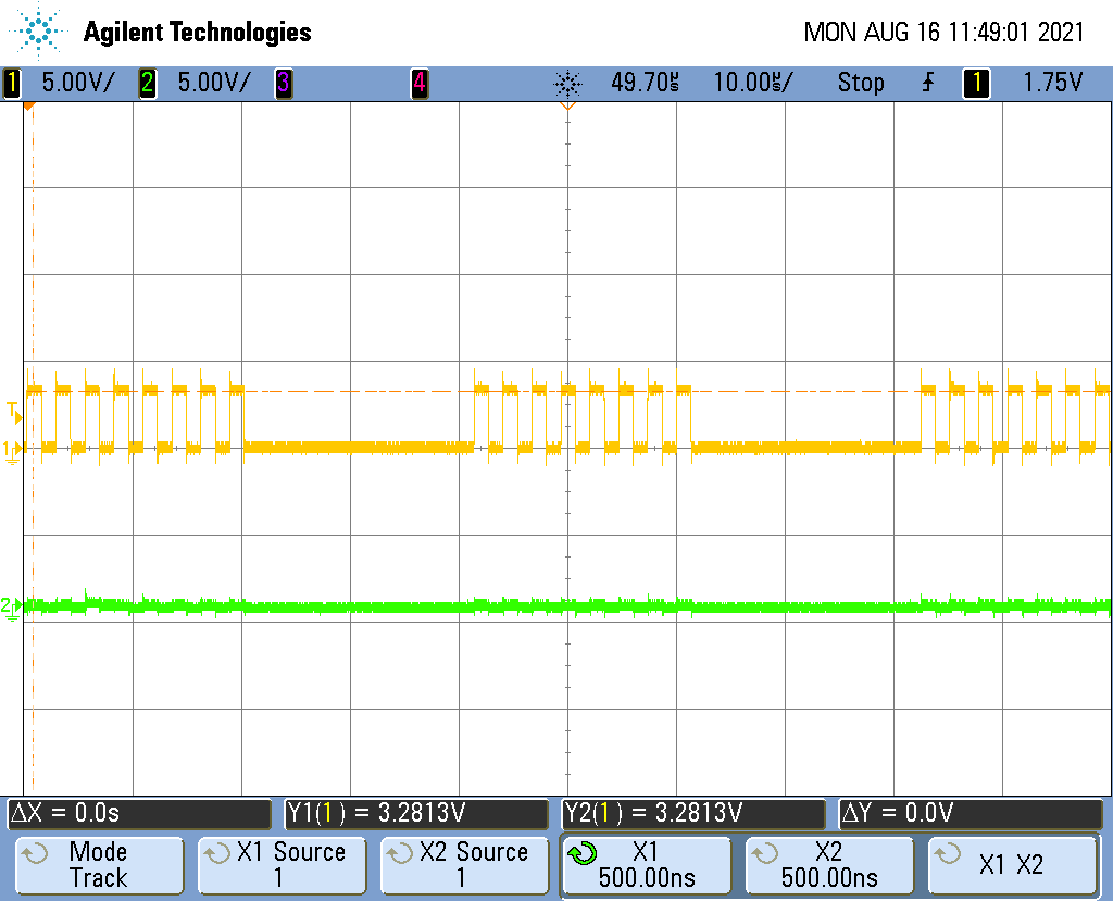
I have some severe problems with SPI communication to ADS1298.

I am trying to read Device-ID register but I don't get any response from the device.

After power-up, I reset the device like this:

	// CS
    HAL_GPIO_WritePin(GPIOD, GPIO_PIN_14, GPIO_PIN_RESET);

    // RESET LOW
    HAL_GPIO_WritePin(GPIOB, GPIO_PIN_8, GPIO_PIN_RESET);
    HAL_Delay(100);

    // RESET HIGH
    HAL_GPIO_WritePin(GPIOB, GPIO_PIN_8, GPIO_PIN_SET);
    HAL_Delay(100);

    // RESET CMD
    HAL_SPI_Transmit(&this->spi_handle, &COMMANDS.RESET, 1, 250);

	while(HAL_SPI_GetState(&this->spi_handle) != HAL_SPI_STATE_READY);

	// CS
	HAL_GPIO_WritePin(GPIOD, GPIO_PIN_14, GPIO_PIN_SET);

After that, I issue SDATAC command:

	// CS
    HAL_GPIO_WritePin(GPIOD, GPIO_PIN_14, GPIO_PIN_RESET);

    HAL_SPI_Transmit(&this->spi_handle, &COMMANDS.SDATAC, 1, 250);

	while(HAL_SPI_GetState(&this->spi_handle) != HAL_SPI_STATE_READY);

	// CS
	HAL_GPIO_WritePin(GPIOD, GPIO_PIN_14, GPIO_PIN_SET);

And then try to read Device-ID:

	constexpr uint8_t reg_addr = 0x00;

	uint8_t opcodes[3];
	opcodes[0] = 0x20 | reg_addr;
	opcodes[1] = 0x00;
	opcodes[2] = 0x00;

	uint8_t receive;

	// CS
    HAL_GPIO_WritePin(GPIOD, GPIO_PIN_14, GPIO_PIN_RESET);

	HAL_SPI_Transmit(&this->spi_handle, &opcodes[0], 1, 250);

	while(HAL_SPI_GetState(&this->spi_handle) != HAL_SPI_STATE_READY);

	HAL_SPI_Transmit(&this->spi_handle, &opcodes[1], 1, 250);

	while(HAL_SPI_GetState(&this->spi_handle) != HAL_SPI_STATE_READY);

    HAL_SPI_TransmitReceive(&this->spi_handle, &opcodes[2], &receive, 1, 250);

	while(HAL_SPI_GetState(&this->spi_handle) != HAL_SPI_STATE_READY);

	// CS
    HAL_GPIO_WritePin(GPIOD, GPIO_PIN_14, GPIO_PIN_SET);

	return (receive >> 5);

but I only receive 0x00. Any ideas what I might be missing? I already checked VCAP1 which is at 1.2V

  • First scope picture: MOSI

    Second scope picture: MISO

    MOSIMISO

  • Hi,

    Welcome to the E2E forum, and thanks for the post.

    It is not clear the initial condition of the device during power-up from the source code and the scope plots. Therefore, would you please verify you are following the Power-Up Timing Diagram (Figure 105) and the Initial Flow at Power Up (Figure 93) after the power-up of the analog and digital supplies? For debug, you may want to try to read from other registers to see if you are able to get any default register values for CONFIG1/2/3.

    How are the hardware RESETn and PWDNn pins connected in your design? Are they tie together or controlled separately in the hardware design? One common occurrence with some hardware designs is the RESETn, and PWDNn pins are connected together. In this case, the device hardware reset may not operate properly when the RESETn pin is issued.

    [FAQ] ADS129x: Why does the Device ID register show the incorrect number of channels?

    [FAQ] ADS129x: I'm having trouble communicating with my ADS129x device via SPI. What debug steps I should try?

    Thanks

    -TC

  • I was just wondering whether it is normal behavior that VCAP is at -1.1V instead of +1.1V if I measure with respect to GND? If I measure with a multimeter across VCAP I get 1.1V as expected. Shouldn't it be enough to just wait 2 or 3 seconds after supplying the board with power to ensure VCAP is charged?

    Ultimatelly I am using a board from Texas Instruments (ADS1298ECGFE-PDK) and I just connect 3.3V, 5.0V and GND (0V) - I don't quite understand why I should worry about the startup - shouldn't the board handle this?

    EDIT: I had to switch JP21. In the original configuration, CS on the pinheader was not connected to CS on the ADS1298 IC. Now it works fine (at least reading the config register)