This thread has been locked.

If you have a related question, please click the "Ask a related question" button in the top right corner. The newly created question will be automatically linked to this question.

ADS1118: Calculation formula for the ADS1118

Part Number: ADS1118
Other Parts Discussed in Thread: ADS1018

Hi,

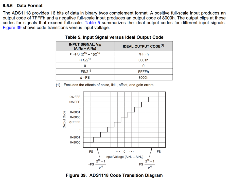
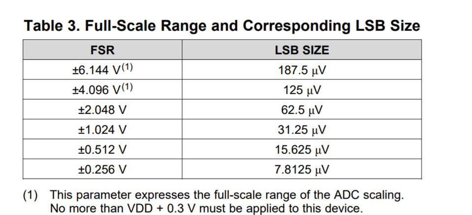
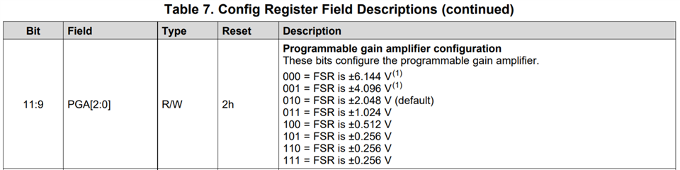
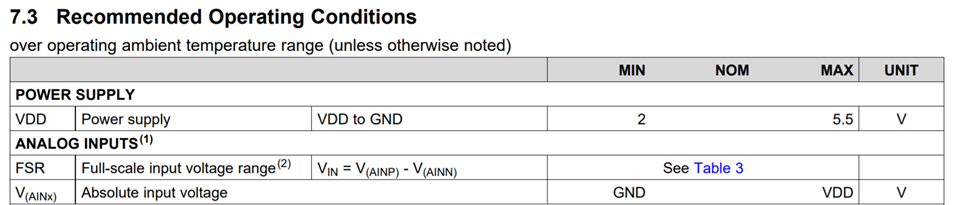
I am using  ADS1118 interfacing with the Nrf52840 controller. Here we are giving the voltage  of (2.8v) to analog channel  2 and  we are getting the output as 7FFF so now  we need to convert the adc value into voltage.

So could you please tell me how to convert the adc value into voltage.

What is the formula to convert the values into voltage? ,can you please tell me what is the internal reference voltage.

  • Hello Chandana,

    The datasheet provides the equation that depends on the Full Scale Range (FS or FSR) with the assumption that V_IN = V_AINP - V_AINN. So when you apply "the voltage  of (2.8v) to analog channel  2" we assume that V_AINP = 2.8V in this case and V_AINN = GND or 0V so that V_IN = 2.8V.

    Looking at the table, we can already see you're applying a voltage that is greater than the full scale range (output code is 7FFFh). Also note, this device uses twos complement to represent a negative number for V_IN (that is, V_AINP - V_AINN < 0).

    The full scale range is determined by the table below and selected by using the PGA[2:0] register

    As noted by the table, +/-2.048V is the default. So, if you didn't change the range, and if V_AINP = 2.8V and V_AINN = 0V, then this result is expected. If you have prior experience with ADCs, we would normally incorporate the reference voltage (and gain) in an equation to determine what the value is. Luckily, all of those things are controlled by the device so we don't need make the equation complicated to incorporate those terms. 

    As for the equation:

    V_input = n_code*(FSR/2^15) -> 2's complement if negative 

    • Where FSR = the positive for negative full scale range depending if a positive or negative V_IN is detected, respectively.

    I explain the equations derivation in a more thorough post here: https://e2e.ti.com/support/data-converters-group/data-converters/f/data-converters-forum/1019712/ads1018-q1-ads1018-q1/3770766#3770766 You'll just have to acknowledge that the ADS1018 is a 12 bit device and needs to 0 pad the end so the equation will be different.

    As a final comment, the footnotes for FSR +/- 4.096V and +/-6.144V does not allow you to apply a voltage higher than VDD which should be no higher than 5.5V. So it is impossible to utilize the entirety of the full scale range for the +/-6.144V, it just allows the user to sense a voltage up to VDD

    Best,

    -Cole

    Edit: forgot to add equation, added some more text, and also added another link