This thread has been locked.

If you have a related question, please click the "Ask a related question" button in the top right corner. The newly created question will be automatically linked to this question.

TLV2556: Zeros

Part Number: TLV2556

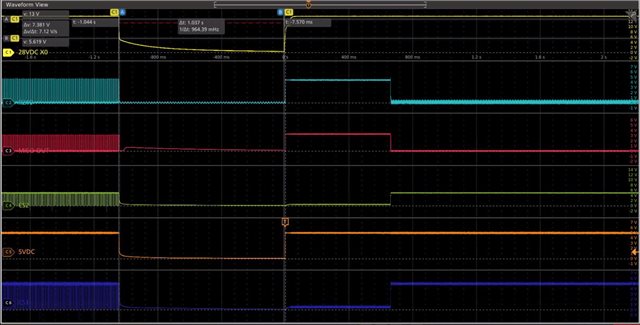
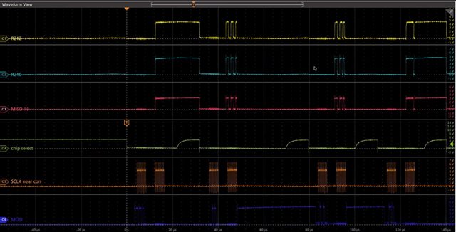
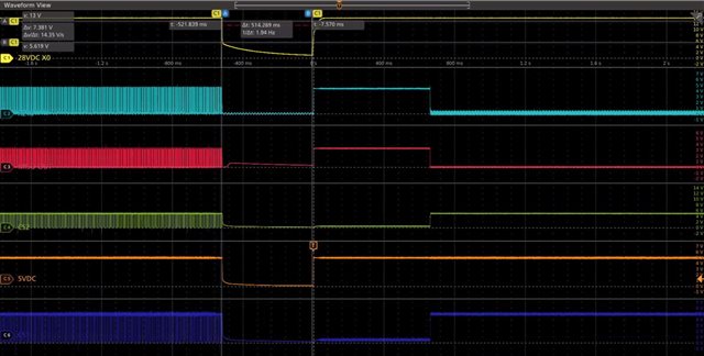
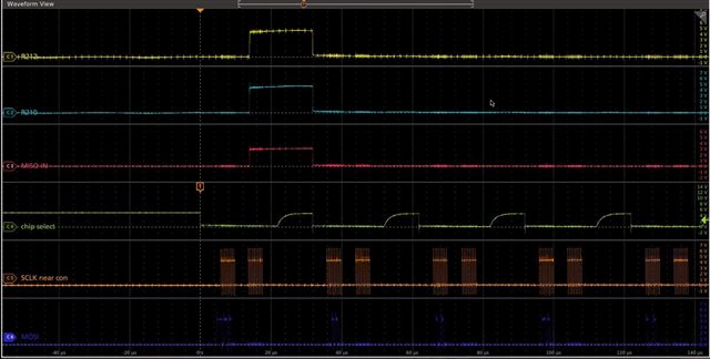
The part responds to a reference readback, but returns zeros for all other channels when power is regained after a brownout less than one second in duration.  Is this a known behavior, or could it  be related to a premature assertion of chip select during power up?

  • Hi Valeria,

    Welcome aboard the e2e Forum!  Can we get some screen shots of the communications to the TLV2556?  The /CS, SDI, SDO, and the SCLK for starters would be good.  Maybe a schematic too if you have one.  How do you detect the brownout condition and then initiate the recovery from the event?

  • Thanks for the warm welcome Tom!

    The brownout is a controlled condition where the supply voltage to the TLV2556 is removed, then reapplied, at varying intervals (actually a blackout, I guess) in accordance with MIL-STD-704 testing at the system level. There are two devices showing the same problem, hence the two chip select lines in the photos.

    Figure 1a:
    5VDC power is applied to the TLV2556 at the trigger point after 1000ms of blackout. Chip select pullups show a 600ms lag behind 5VDC.


    Figure 1b:
    SPI communication shows all data is being returned correctly (about 10s after power is restored).


    Figure 2a:
    5VDC power is applied to the TLV2556 at the trigger point after 500ms of blackout. Chip select pullups again show a 600ms lag behind 5VDC.


    Figure 2b:
    SPI communication shows only the reference readback is returned correctly (also about 10s after power is restored).


    The analog input pin voltages and the REF+ pin voltage are all derived from the 5VDC rail. It is only the chip selects which are derived elsewhere. While understood to not be best practice (a fix is in the works), it's not clear that the chip select timing is the root issue.

    Thank you so much for your help!

  • Hi Valeria,

    So, it's only an issue if you try to restart the system after 500mS?  In Figure 2a, it looks like there is still residual voltage on C3 and C5.  Can you verify what that voltage level is and what's the difference between those voltages WRT Figure 1a?

  • C3 is the MISO output from a buffer IC after the TLV2556 so likely isn't relevant for this issue. C2 shows the true MISO output from one of the devices. C5 is the 5V rail (VCC) powering both devices as labeled on Figs 1a/2a. The exact time needed is to be determined for our system, but it appears that beyond one second, the device restarts just fine. The system is currently being modified to use a different 5V rail which is software-controlled. This should help answer the question of what voltage decay level is necessary for things to work. In the meantime, any information on this requirement would be helpful!

  • Hi Valeria,

    Let the ABS MAX Ratings table be your guide.  If the 5V supply drops out, the analog and digital I/O should also drop out.  Any signal that exceeds Vcc by more than 300mV could cause unwanted behavior from the TLV2556.