This thread has been locked.

If you have a related question, please click the "Ask a related question" button in the top right corner. The newly created question will be automatically linked to this question.

ADS1298: ADS1298

Part Number: ADS1298

Hello,

We build the new version of PCB for ADS1298 with reference of sbau171d document of TI. We currently communicate ADS1298 with Raspberry Pi.

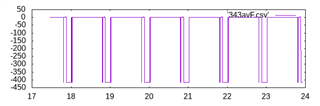
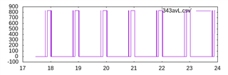
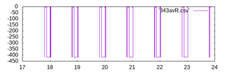
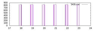
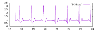
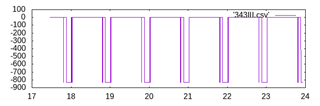
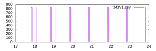
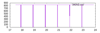
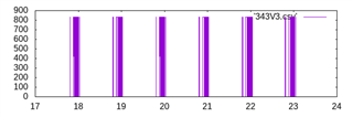
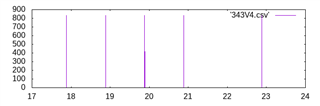
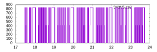
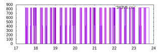
But we only get the lead 2 graph. some time we get V4 with lead 2. Please Help.

The Resistor logs are as per following

All values are in Hex.

Device type 146

LOFF             0X3

CONFIG3     0Xdc

GPIO read    0X0

CONFIG1      0X85

CONFIG2      0X10

CONFIG4      0X2

RLD_SENSP   0X0

RLD_SENSN   0X0

WCT1                0Xa

WCT2               0Xe3

LOFF_SENSP   0Xff

LOFF_SENSN  0X2

PACE                  0X0

RESP                  0X0

LOFF FLIP          0X0

LOFF_STATP      0X0

LOFF_STATN      0X0

CH1SET              0X0

CH2SET               0X0

CH3SET              0X0

CH4SET              0X0

CH5SET              0X0

CH6SET              0X0

CH7SET               0X0

CH8SET               0X0

Here are the voltages of some test points

  1. VSSA      -2.5V (w.r.t. GND)

  2. VDD         +3.3V (w.r.t. GND)

  3. VrefP         0.88mV (w.r.t. GND)

  4. VrefP         2.042 (w.r.t. VSSA)

  5. VerfN         -2.5V (w.r.t. GND)

  6. VCAP1      -1.228v (w.r.t. GND)

  7. VCAP1       1.198v (w.r.t. VSSA)

  8. VCAP2       0.37V (w.r.t. GND)

  9. VCAP2       2.52V (w.r.t. VSSA)

  10. VCAP3       4.43V (w.r.t. GND)

  11. VCAP3       6.91V (w.r.t. VSSA)

  12. VCAP4       -1.284 (w.r.t. GND)

  13. VCAP4        1.20 (w.r.t. VSSA)

  14. VDDA          +2.5 (w.r.t. GND)

  • Hi Koustubh,

    Thanks for the post.

    It is difficult to know what may be the issue from the information provided. However, there are some debug steps that you can try to isolate the issue. My suggestion is to make sure your signal-chain data capture is correct with your Raspberry Pi. You can verify the data capture for all channels using the internal-generated test signal.

    I do not see any issue with the register setting of the device. However, the VREF (VREFP-VREFN) voltage seems to be slightly different from the expected voltage for the internal reference of 2.4V. Please verify if this is a measurement error or issue with the hardware board. If the hardware design is not using Daisy-chain mode, you need to set the DAISY_ENB bit (CONFIG1.6) to 0.

    Are all these tests results done with an ECG simulator?

    Thanks

    -TC

  • Hello TCT,

    Thanks for the replay.

    Yes these test results are with an ECG Simulator.

  • Hi Koustubh,

    Thanks for the information. Please see the debug suggestion for your issue.

    Thanks

    -TC