This thread has been locked.

If you have a related question, please click the "Ask a related question" button in the top right corner. The newly created question will be automatically linked to this question.

DAC8775EVM: DAC8775EVM GUI problem

Part Number: DAC8775EVM
Other Parts Discussed in Thread: TIPD215

Hello,

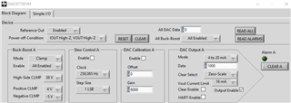
I am using DAC8775EVM with the GUI tool for configuring 4-20mA. I am unable to get and current at the output. I have used the below jumper settings.

JP9 - Installed

JP11 - Installed

JP13 - Not Installed

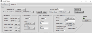
But when I configure the DAC to 0-5V mode, I get the output. What could be the reason ?

Thanks in advance

  • Amit,

    I have a DAC8775EVM set up with the default settings of JP9, JP11, and JP13 all not installed. I find that starting with the default is the easiest setting. This means that the DVDD is supplied by the SM-USB-DIG. I use a 12V supply that is connected to AVDD/PVDD and this powers the EVM. 

    I do a reset at the beginning, and then enable the reference out. Then I enable all the buck boost supply. I can also set the Power-off condition to be IOUT High-Z and VOUT High-Z so that I don't see the extra loading from a 30kΩ resistor. 

    After that I enable the output for Channel A. I can set the DAC data and see the output for any of the ranges. For example, I can set the DAC code to 1000 hex with the VOUT range of 0-5V and I get  0.31235V (where the expected is 5/16 = 0.3125V). I can then set the output to 4-20mA. This resets the DAC code to 0000 hex, and the output goes to 3.9905V with a 1kΩ load. Setting the DAC code to 1000 hex, this sets the DAC output current to 5mA, and the output goes to 4.988V. 

    I've also tested this with JP9 and JP11 installed and this also works in the same way. I got the same outputs.

    I would be careful not to have the EVM powered up so that you don't have the case where JP9 is installed and JP11 not installed. In this case, the DVDD LDO is enabled and would try to power the power of the SM-USB-DIG. In that case, there is contention between the USB power and the device DVDD LDO. If this is the case, there's a chance that the DVDD LDO or the SM-USB-DIG might be damaged.

    Have you checked the remaining channels on the EVM? I would want to know if the other channels are responsive to the voltage or current ranges.

    Joseph Wu

  • Joseph,

    I can get the output in voltage mode 0-5V, 0-12V. But the 4-20mA mode does not give any output? I have even tried with the internal LDO(default settings of JP9, JP11). Is it possible that the board is partially damaged? How can I verify if the board is still functional?

    Thanks

  • Amit,

    I think it's unlikely that the EVM board is broken for just the IOUT,  when the VOUT is working well. I'd like to just check a couple things about your setup.

    First, is the VOUT working on all channels? Have you checked several values? 

    Second, does the IOUT not work on all channels? I just want to make sure that it's only one channel that isn't working.

    Last, how are you measuring the current? I would use a load resistor and then measure the voltage, do it this way instead of using the meter as an ammeter. I've made measurements before and gotten only zeros. The person who used the meter before me had blown the series fuse and open-circuited the ammeter.

    Regardless check these things and post back.

    Joseph Wu 

  • Thanks, Joseph, The multimeter series fuse had blown. Things are once again working fine on the EVM.

    But I am unable to see the output on TIPD215 board. I have created a copy of TIPD215. Please find the attached schematic. I am using the same SPI code and register settings that I had used on DAC8775EVM, but there is no output on TPID215 copy board.

    What could go wrong ?

    https://www.ti.com/tool/TIPD215

    vs 

    DAC8775EVM

    vs

    my schematic(attached)

    my_schematic.pdf

    Thanks in advance

  • Amit,


    It looks like you copied the schematic directly from the TIPD215 board. Did you have exactly the same BOM? Or did you need to make any substitutions?

    If the schematic is the same, the board should work. It's even similar to the DAC8775EVM board. The EVM board has many more jumpers and test points, but the layout is the same.

    I would check to see that the devices are soldered down correctly. Then I would check the voltages around the board to make sure they are where they should be. You can use the EVM to compare the two boards. I would also see if you write to the device and read back from it.

    There are many things that could be wrong, but you should be able to verify some things on the board.


    Joseph Wu