This thread has been locked.

If you have a related question, please click the "Ask a related question" button in the top right corner. The newly created question will be automatically linked to this question.

ADS8688A: ADS8688A protection

Part Number: ADS8688A
Other Parts Discussed in Thread: OPA2188, ADS8688

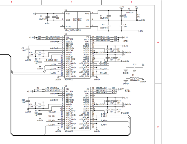
ADS8688A was used in a power source device. when power up, some switches opened/closed, 8688 got malfuction sometimes. three phenomenon

1、ref voltage changed to 3.7V from 4.096V or the voltage is drifting

2、all sample data is 0xFFFF or 0x0000

3、chip may get hot

the circuit is as follow, 

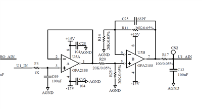
how can i solve this,  i have tried to add diode to U1_in and tvs to u1_ain, it did not work

  • ADS8688A has been replaced and soldered manually, did this affect this chip?

  • Hi nirvana_xun,

    Soldering manually is okay as long as you can make sure no short which is unexpected and good connection which is expected according to the datasheet. I need more information to help me understand the issue:

    1. Did the chip overheating happen immediately after the chip was powered up? or it happened after running for a while?
    2. Do you know if switch opening or closing affects +5V/+3.3V power supplies or input signal (transient signals)?
    3. When the code 0xFFFF or 0x0000 was found, can the ADC recover by itself or you have to cycle the power supplies(+5V/+3.3V) to recover the ADC?

    A solid ground plane is recommended especially when you have two ADCs on a circuit board. I do not know where the F1 is on the pcb board, however the AGND and DGND on each ADC should have a short connection path. Therefore, a dedicated ground layer/plane is recommended. 

    The DAISY and /REFSEL pins should be connected to DGND if there is no solid ground plane. C15 should be connected AGND, not DGND.

    When designing a protection circuity for analog input, a series resistor is very helpful to limit the current and protection the input. Please see TI Precision Labs ADC - Protecting ADC with TVS diode for more details.

    Best regards,

    Dale

  • 1、chips were soldered by a ten years hardware engineer, we had soldered for 5 or 6 times, every time the ref did not work,recommended soldering temperature?

    2、in the analog ports the transient signals is about 10~20V when the cabinet is connected to a solid ground

    3、somed chips get hot shortly after power up when broken

    4、when can not read data from 8688, sometimes cycling the power works, sometimes does not work

    5、we do have resistor in the analog input path, not 1kΩ  as in the app note, just 100Ω

  • Hi nirvana_xun,

    1. I do not think your soldering caused the problem if you can confirm no unexpected short and the expected connections are good.

    2. Is it possible to have a situation:  the 20V transient or +/-15V power supply of OPA2188 is available before the +5V of the ADC is powered up?

    5. The 100ohm does not help too much for limiting current.

    I suggest you to do the following experiments as I highlighted in my previous post:

    • Connect the DAISY and /REFSEL pins to the DGND (close to the ADC) instead of AGND.
    • Since you are splitting the ground and not using a solid ground plane, so short the AGND and DGND as close to the ADC as you can for debug purpose.

    Best regards,

    Dale

  • I will confirm soldering

    The ±15v power is generated by 5v power, so 8688 powered ups first

    We measured avdd when swtichs operated, the pulse is about 14v. And had negative pulse, about -7v, will this affect the chip?

    Also measured Apn signals when switch closing, the pulse will not exceed 14v

    Does daisy/refsel pin affect chip configuration when chip already powered up

  • when the switch operated, chip malfucntion, chip got hot. when powered up again, the chip worked again. did the chip damaged, when the ref drifting?

  • Hi nirvana_xun,

    You need a TVS diode on AVDD to protect the device. The maximum AVDD is 7V which has been specified in the Absolute Maximum Ratings table on page 5 in the ADS8688A's datasheet. Your 14V supply definitely may damage the ADC device.

    When AVDD is powered up firstly, a 14V signal on AIN_xP pin will not damage the device. The device can accept +/-20V signal without damage.

    The DAISY and /REFSEL should be connected to the DGND, not AGND for whatever situations.

    I do not know what you mean "worked".  The device is not damaged if the Vref is correct and the conversion data retrieving from the device is correct. However, please notice that the key information below which was copied from the datasheet:

    Stresses beyond those listed under Absolute Maximum Ratings may cause permanent damage to the device. These are stress ratings only, and do not imply functional operation of the device at these or any other conditions beyond those indicated under Recommended Operating Conditions. Exposure to absolute-maximum-rated conditions for extended periods may affect device reliability.

    Best regards,

    Dale

  • i changed the mother board, also the power source of analog board, the ads8688A did not malfunction any more. measuring the power supply of 8688, the wave still was not so good. 

    whether the peak voltage is brought in by the probe or it really existed? any suggestion?

  • power of the ADS8688 was come from the mother board

  • Hi nirvana_xun,

    Are you measuring the supply for AVDD in your screenshot? What's the device you are using to generate on the mother board?

    Regards,

    Dale

  • the wave is avdd in the pics. the mother board generated the avdd of 8688 through a isolating switch power supply.

    switch power supply: 24v in  5v out 20w, isolating voltage 1500VDC

  • Hi nirvana_xun,

    According to the screenshot you showed, you need a LDO to get a clean supply for the ADC's AVDD. You can generate an isolated DC power supply voltage which is higher than 5V (Viso), then a LDO can take the Viso and generate a regulated 5V for the AVDD. Below is a solution I used, FYI:  12V->TPS7A4700->SN6505->Transformer->TPS7A4700 for 5V output->ADC. 

    Regards,

    Dale

  • we will try this method. thx