This thread has been locked.

If you have a related question, please click the "Ask a related question" button in the top right corner. The newly created question will be automatically linked to this question.

TLA2518: On-the-Fly Mode timing

Part Number: TLA2518

Looking at Figure 32 (On-the-Fly Mode), I am having trouble understanding the timing relationship between CS and acquisition/conversion.

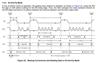
My understanding is that conversion begins at the rising edge of CS, and that conversion data cannot be read (i.e. SCLK must remain inactive) for tCONV=600ns after this rising edge. Then, 5 SCLK periods are required to select the next channel -- at 60 MHz this is 83ns. If acquisition begins immediately after this fifth SCLK, then an additional tACQ=400ns must pass before the next CS rising edge. Given this, it looks like the minimum conversion period is 600+84+400 = 1083ns. Am I misunderstanding something? Is there a way to achieve a 1000ns conversion period using On-the-Fly Mode?

Thank you,

Jonathan

  • Jonathan, 

    You should be able to achieve full throughput rate with 60Mhz, but your concerns are valid. I need some time to reach out to the team to better understand this and get back to you.

    Regards

    Cynthia

  • Hello Jonathan,

    After reviewing it, the five clock pulses should not be considered separately, they can occur during the conversion time. This means that the data transmission needs to be fast enough to occur during the desired cycle time (minus 200ns minimum CS high time) to meet desired cycle time.

    Regards

    Cynthia

  • Thank you Cynthia for your response.

    Perhaps I am misunderstanding the meaning of tCONV. If I start clocking in the Channel ID, I am also clocking out the previous channel's data. If I drive CS low and start clocking in after minimum 200ns CS high time, won't I be violating tCONV?

    Thank you,

    Jonathan

  • Hello Jonathan, 

    I continued to push this discuss this with my team, as I agreed with your way of thinking, and below is a more detailed explanation.

    The datasheet and figure 32 demonstrate a communication with a Latency 0.

    To achieve this

    Latency 0 operation (shown in the datasheet, specifically figure 32)

    1. Host pulls CSz low after tCONV.
    2. The first 5 bits on SDI indicate the next channel to be selected. Multiplexer switches to the next channel on the 6th clock
    3. From 6th clock until the next CSz rising edge will be acquisition time.

    Note this is aligned with your original understanding of the initial 5 SCLK being in addition to the conversion and acquisition time. The team discussed this, and if the input drive circuit can adequately settle within taqc_min(400ns) – 5*SCLK, then the acquisition time can be shorted to make up the time for the 5 initial clock pulses and meet the 1MSPS sample rate. The device will still operate as expected if the acquisition time used is less than t_acq min

    Now, when I mentioned bring up CS before t_conv and clocking out data, your understanding was correct that the device would clock out the previous conversion data.

     I hope this helps

    Regards

    Cynthia

  • Hello Cynthia,

    My takeaway from your reply is that tack_min (400ns) is not a strict limitation, but is malleable depending on the input drive circuit.

    Please help me understand exactly what you are referring to with the 'input drive circuit'. Are you referring to the analog circuitry within the TLA2518, as in Figure 22?

    How will I know if the internal circuitry will settle in less than 400ns?

    Thank you,

    Jonathan

  • Your take away is correct. 

    The input drive circuit is the input signal source to the ADC, for example a sensor, or a power supply rail, and such. Not the TLA2518. 

    The signal source then needs to be able to drive the ADC input within the acquisition time to half a least significant bit (LSB) for the ADC measurements to be accurate. To do this, the C_SH capacitor shown in Figure 22 above needs to be charged within an LSB of the input signal voltage within the acquisition time. 

    For more information on this, I recommend TI precision labs ADC ~click here~

    specifically the following videos:

    SAR and delta-sigma: Basic operation

    Driving SAR ADC without amplifiers

    Regards

    Cynthia