This thread has been locked.

If you have a related question, please click the "Ask a related question" button in the top right corner. The newly created question will be automatically linked to this question.

DAC61402EVM: DAC61402 Reference not measuring 2.500V

Part Number: DAC61402EVM
Other Parts Discussed in Thread: DAC61402, DAC81402

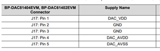
Good day. I have a question about the reference on the DAC61402 as part of the BP-DAC61402EVM eval board. I was able to get the software for the BP-DAC61402EVM to communicate with the controller and the Launchpad controller has been successfully updated/verified with the latest firmware per the datasheet instructions. Pins 1-5 on J17 are at the appropriate voltages as well. I tried measuring the DAC's internal reference and got 2.404V. There is no jumper on J16 so the external 2.500V reference is disconnected. Thinking that the DAC might have been damaged from ESD, our re-work person replaced the DAC on the eval board with one of two that we purchased from a popular online vendor (while carefully following ESD precautions this time). The internal reference of the new DAC measured 2.386V. Based on the datasheet for the DAC61402, this is outside the min/max for the 2.500V internal reference. I can disable the internal reference by toggling bit 13 of the GENCONFIG register. However, the datasheet (and software) states that bit 14 is the ref powerdown bit. When we toggle that bit, we get no response from the DAC (the internal ref doesn't change). I have probed the SPI lines from the controller and the clock, SDI, and SYNC all appear to be transmitting the correct data. On top of all this, I still am unable to get a non-zero output on any of the DAC channels when using either the internal reference or the external reference (which is 2.500V). Is there a particular reason that the internal references measure around 2.400V instead of 2.500V? I'm using a Fluke189 with Kelvin leads so I don't believe a drop in the probe leads are giving incorrect readings. Any suggestions as to what the issue might be would be greatly appreciated.

Thanks,

John B

  • Hi John,

    1. Could you able to read / write internal register ? 

    2. What is state of voltage at REFIO after power on ? and after setting  disable ref power down bit ( internal reference select bit).

  • Hi Anbu and thanks for your reply. I'm finding that reading from or writing to the registers is inconsistent. For instance, when I'm on the Register Map screen of the GUI, the 15 bits will be configured in a state such as 0 1 0 0 1 0 0 ..... When I write to or read from the register, bits will sometime flip seemingly at random. The state of the REFIO after power on is 0V with no jumper on J16. When I flip the bit to enable the reference, the internal REFIO goes to 2.400V. A DSO scope on the SPI lines reveals that some of the data is not being written to the chip unless the "write register" button is pressed a few times. In short, I'm getting weird behavior from the setup. DO you think this might be a software issue? I'll continue to investigate.

  • Hi John,

    1. Did you checked all power are ok,  we need to ensure device read/write must be working before doing further investigation.


  • Anbu, I have verified that pins 1 and 4 of J17 are 5.0V and all others are at ground. We went ahead an ordered another DAC61402 eval board thinking that perhaps the board was damaged through ESD or handling. I connected the new eval board to the Launchpad and connected to the PC through the USB. I'm still seeing the same issues. The default INT/EXT reference switch is set to INT but I don't get 2.500V--just 0V. Toggling the REF_PWDWN_EN pin from 0 to 1 does nothing. However, toggling the BG_TO_ALARM_PAD from 0 to 1 seems to enable the internal reference but it outputs 2.378 as before. Again, this is a completely new eval board with accompanying DAC61402.

    I don't know if this information is useful but I noticed that when I try and connect the eval board using the default port in the Options menu of the DAC Eval application, it cannot find the hardware. If I switch ports in the Options menu, I can then connected successfully according to the app. I reloaded the Launchpad with the acctrl.bin file found at ...\Downloads\BP-DAC81404EVM_1.0.0_installer_win\install_image_BP-DAC81404EVM\BP-DAC81404EVM\app\firmware. The file is dated 1/7/2021. Even if the issue is with the SPI from the Launchpad, that doesn't explain why the DAC61402 internal reference is close to 2.4V instead of the advertised 2.500V.

  • Hi John,

    At present i don't have DAC61402 EVM with me.

    Give me some time I,   will check internal team for EVM and try my self  to see what going wrong.

  • Hi John,

    I got EVM and able to generate DAC output . Also, i can able to get internal reference 2.5 V. By default internal reference is disabled.

    1. Can you write following write and check whether internal reference coming at TP11.

    You should get 2.5V internal reference.

    2. Which channel are you measuring for DAC output ? DAC61402 , DAC-B and DAC-C only enabled.

  • Thanks for procuring an eval board to verify it's operation. I'll following your suggestions this weekend as I haven't had enough time to sit down and validate my own DAC61402 based on the new information. I'll let you know what I find here shortly.

  • Anbu, I entered the words into the registers you specified and I was able to get 2.500V at the internal reference output (J16 removed) so thank you for that. However, I have not been able to get any voltage level out of the either DACs B or C. My jumper settings are all at the default positions listed in the EVM guide. Entering numerous values into the DAC_B_DATA and DAC_C_DATA and DACRANGE registers (or using the values on the Quick Start page) does not generate any DAC output voltage. Pins 1-5 of J17 are all at the correct voltage.

  • I was playing around with the DACPWDWN register that was set to 0x0000 and I toggled the respective bits for both DACB and DACC from 0 to 1 and back to 0 and I was able to measure a voltage on the output. Both have 10V on AVDD and their range is set accordingly. However, I thought I had the 12 bit DAC61402 because I set the DACB count to 4095 and I only got 622 mV. I then set the DAC count to 32768 and got exactly 5.00V (DAC count set to 2^16 - 1 gives 10.00V). Apparently, I have the 16 bit version although the eval board I'm using has a label in the corner with text that says "BP DAC61402". Am I correct in assuming that the DAC61402 is only 12 bits?

  • Hi John,

    DAC register are MSB aligned and LSB (4 bits) padded with zeros for 16 bit register.

    DAC61402 device will take 12 bit data as shown in figure.  Hope now you understand your are getting correct output which is related to 12 bit resolution.  

  • Thank you for answering my initial question. I did enable the 2.500V reference with your help and get an output from the DAC once I understood that it could run in either 12 bit and 16 bit mode. I was unaware of this and presumed that the DAC61402 was only capable of 12 bit operation regardless of the DACn register settings that, in turn, led me to believe that I was dealing with the DAC81402.

    Thanks again!