This thread has been locked.

If you have a related question, please click the "Ask a related question" button in the top right corner. The newly created question will be automatically linked to this question.

ADS8568: ADC SPI communication

Part Number: ADS8568

Hi Team,

The customer is having issues with the ADC SPI communication. Kindly refer to the information below:

I can read te data but from time to time the ADC « fails » to convert data.

I follow the datasheet and code a SPI in a FPGA to get the data from the ADC.

So I send a conversion request on CONSTA, B, C and D at the same time, then wait for Busy to drop and put 0 on FS to read the data on SDO_A, B, C and D. The SCLK is generated only when the data are red from the FPGA.

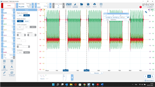
SCLK = 2,75 MHz -> clock to synchronize the data on SDOA, B, C , D

Conv Clk = 50 kHz -> frequency to initiate a conversion sequence
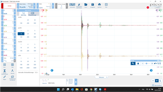
 

Green trace : SCLK

Red trace : FS

Blue trace : CONVST

Brown trace : Busy


The two first pictures show the correct behaviour, I can read the data correct

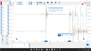
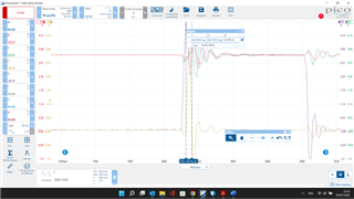
The Following picture show the signals when the conversion fails. Busy picks up for a couple of ns an drops immedialtely, apparently the conversion fails as I can’t imagine that the conversion is so fast. It takes usually (on a successful conversion) around 2 µs to make a conversion.

I don’t think the ADC has an issue, there is probably something I am missing. Any advice help would be highly appreciated.

I hope you can help the customer.

Thanks!

Regards,

Marvin

  • Hi Marvin,

    Our applications engineer will respond your post after the holiday. 

    Thanks&regards,

    Dale

  • Hi Dale,

    Thank you. I am looking forward to your teams response.

    Regards,

    Marvin

  • Hello Marvin,

    The images are too small to be able to decipher any information from the, would you reupload with a bigger resolution? 

    It is odd that the same action would result in two different actions. Is there a pattern to when the failed conversion happens? or is any specific action taking place in the system when this occurs, any switching?

    From what i can gather from the images, there seems to be large overshoot on the digital bus, this may be big enough to be triggering incorrect state changes. Are these connections on PCB or on lose wires? I would suggest trying to get these signals to settle faster. If it on PCB, adding a small resistor in series in the digital lines will help. If it is loose wires, then having as short connections as possible would be beneficial 

    Regards

    Cynthia 

  • Hi Cynthia,

    Here is the Images as requested:

    Trame oscilloscope.zip

    Is there a pattern to when the failed conversion happens? or is any specific action taking place in the system when this occurs, any switching?

    There is no particular action when it occurs.

    From what i can gather from the images, there seems to be large overshoot on the digital bus, this may be big enough to be triggering incorrect state changes.

    The overshoot could be the reason for the failure. But can you explain why it would stop the conversion in the ADC (Busy drops after some ns). Maybe if the ADC assumes the FS or CONVST to be at 0 ?

    If it is loose wires, then having as short connections as possible would be beneficial 

    Connections are loose wires from the FPGA DE10 board (GPIO port) to the ADC board J11 connector, they are short wires RS ref : 791-6450. Is there a way to dampen the signals on a loose wire like this?  

    Thank you for helping!

    Regards,

    Marvin

  • Hello Marvin, 

    It is very difficult to know how the device is interpreting the overshoot, i think the first focus should be to improve that and see if the results improve.

    Since there is more than one board being used, would you confirm that the ADC has decoupling capacitors placed  close to the power supply pins, and all other devices being used also have well placed capacitors?

    It is helpful to have solid ground connections between all equipment being used. As for the wires, if possible, twisting each cable with a ground cable. this would essentially double the number of wires used. 

    Or, FPGAs usually support the capability to change the driver strength, or also can be seen as the slew rate control, if so, decreasing this would be helpful in this case. 

    Regards

    Cynthia


  • Hi Cynthia,

    Here is the manual of the FPGA dev board (DE10-Lite) for reference. As you mentioned, there are no resistors between the FPGA and GPIO port on the FPGA board (see sheet 31 of the enclosed pdf file DE10-Lite_User_Manual). But there are resistors on the ADC board. should there be an additional resistor between them? if yes, what value of the resistor is advised in this case?

     DE10-Lite_User_Manual.pdf

    Regarding the decoupling capacitors on the ADC power supply, caps are already installed as per the schematic on sbau193e.pdf. Should the "DNP" caps need to be populated also?

    The image below shows the selection on the pin planner in Quartus II, but if something different from 3.3 V LVTTL is selected, the compilation usually fails.

    I hope you can help further.

    Regards,

    Marvin

  • Hello Marvin, 

    This is good information, the customer is using the EVM for the ADC and an evaluation board for the FPGA. There should be no need for a greater resistance on the digital bus if the wires between the two boards are short and twisted with ground connections.

    If the DVDD is set to 3.3v, this explains why communication only works when using a protocol that is based on 3.3v level. Is al equipment being used have ground connections between them, ei, power supplies, all PCB boards?

    As for the FPGA, we are not familiar with this, they will need to reach out to the FPGA provider to control the driver strength.

    Perhaps an easier option is to slow down the sampling rate. Decrease the sampling frequency, this should helps to settle the digital bus. If with the improvement signal integrity there are no further BUSY issues, then this indicates that this was the source of the issue.

    Regards

    Cynthia