Other Parts Discussed in Thread: INA821, LM27762, , ADS1285, ADS1260
Hello experts, I tried to use the LM27762 to convert the +5V power supply into a dual power supply +-5V for the INA821. Figure 1
According to Figure 2, I will eventually output a +-4V signal, so how should I design the ADC sampling circuit?
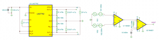
This is just a demonstration diagram a bit casual, so there INA821 isn't power decoupling capacitors.
Figure 1
-------------------------------------------------------------
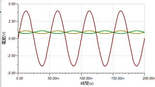
Figure 2
-------------------------------------------------------------
I have an ADS1256 by my side.
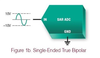
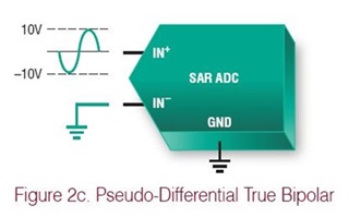
Is this a single-ended bipolar? Or pseudo differential?
And do I need to isolate the GND? I don't understand sorry.
-------------------------------------------------------------
-------------------------------------------------------------