This thread has been locked.

If you have a related question, please click the "Ask a related question" button in the top right corner. The newly created question will be automatically linked to this question.

ADC12DJ3200: JMODE 0 Data Capture

Part Number: ADC12DJ3200

Hi,

We have a custom board with ADC12DJ3200 ADC and Kintex UltraScale FPGA from Xilinx. We are using JMODE 0.

I am using the KCU105 reference design for JMODE 0, but the FFT is not fine.

So I tested short transport test pattern to check if the transport layer arrangement is correct, but even that didn't come fine.

As I am using the reference design, I don't expect the transport layer arrangement to be wrong. But I have no clue about what I am missing.

The sampling frequency is 1600MHz, K=4, Line rate is 6.4Gbps.

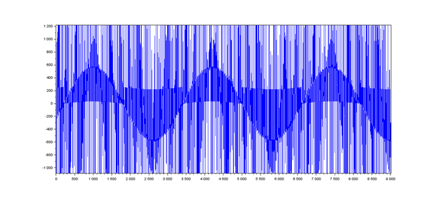
I have attached the screenshot of the Slice outputs of the reference design (probe0 to probe19 corresponds to slice_21 to slice_40 respectively and probe20 is the 240 bit transport layer output).

Looking forward to your support.

Thanks.

  • Hi Ayana,

    Kindly help me understand what a slice output means. Is there a raw lane data capture that you can share?

    Regards,

    Ameet

  • Hi Ameet,

    I will share the lane data capture.

    I have mentioned slice output in reference to ADC12DJ3200+KCU105 JMODE 0 design firmware from TI.

    The transport layer output is 240bit = 20samples * 12bits, these 20 samples are the slice outputs.

    Thanks,

    Ayana

  • I have attached the raw data (IP output) for each lane and also the ADC register values that I have written.

    jmode0_pattern_lane_data_raw.zip

    2275.ADC_Config.txt
    The following is the data being written to the ADC. The first 4 hex digits has the R/W bit followed by the ADC register address.
    The next 2 hex digits is the data written to respective ADC register.
    
    x0000, xB0
    x0030, xFF
    x0031, xFF
    x0032, xFF
    x0033, xFF  
    x0048, x07  
    x0060, x01
    x0200, x00   -- Disable JESD  
    x0061, x00   -- Stop calibration
    x0201, x00   -- JMODE 0 is selected
    x0202, x03   -- Program KM1 (K-1) , K = 4, KM1 = 3
    x0204, x03   -- Scrambler enabled, Signed 2's complement data format, ~SYNCSE used as ~sync
    x0205, x05   -- JTEST Test pattern control register
    x0206, x00   -- DID = 0
    x0211, xF2
    x0212, xAB
    x0213, x0F   -- Enables overrange status output pins
    x0061, x01   -- Enable calibration
    x0200, x01   -- Enable JESD
    x0210, x01   -- BOOST = 1
    x0216, x02
    x0219, x02
    x02B1, x05
    x02B0, x01    
    x02B5, x00
    x02B6, x00
    x02B7, x00
      

  • 0x0060, x01

    x0206, x00   -- DID = 0

    x0210, x01   -- BOOST = 1

    x0216, x02

    x0219, x02

    x02B1, x05

    x02B5, x00

    x02B6, x00


    x02B7, x00

    The above mentioned register writes are not need since they are default values loaded from the fuse once the device is reset. which you do by writing 0x00 with value of xb0. Please note you add some delay around ~150msec after you reset the device for fuse to load. 

    Regards,

    Neeraj

  • Hi Neeraj, 

    We are already providing few milliseconds delay after writing the register 0x000. Also I removed the registers that you mentioned.

    Still the FFT is not fine. I have attached the updated register map and the time domain plot of the captured data. The data is captured for 1MHz, 0dBm input.

    Thanks,

    Ayana

    2148.ADC_Config.txt
    The following is the data being written to the ADC. The first 4 hex digits has the R/W bit followed by the ADC register address.
    The next 2 hex digits is the data written to respective ADC register.
    
    x0000  xB0
    x0030  xFF
    x0031  xFF
    x0032  xFF
    x0033  xFF   
    x0048  x00  
    x0200  x00   -- Disable JESD  
    x0061  x00   -- Stop calibration
    x0201  x00   -- JMODE 0 is selected
    x0202  x03   -- Program KM1 (K-1) , K = 4, KM1 = 3
    x0204  x03   -- Scrambler enabled, Signed 2's complement data format, ~SYNCSE used as ~sync
    x0205  x00   -- JTEST Test pattern control register
    x0211  xF2
    x0212  xAB
    x0213  x0F   -- Enables overrange status output pins
    x0061  x01   -- Enable calibration
    x0200  x01   -- Enable JESD
    x02B0  x01 
    

  • Hi Ayana,

    The lane data that you have sent me seems accurate, so there must be an error in the way it is mapped to samples in the transport layer. The following sequence will recreate the samples on each lane (assuming your working on the raw lane output of the JESD IP):

    1> Byte reverse each line in the file. This is essentially a byte reverse of the 32 bit lane data exported in each cycle.

    2> Concatenate lines 1 and 2, 3 and 4, 5 and 6 and so on. This is equivalent to concatenating two successive cycles of data to get a 64 bit packet

    3> Discard the 4 LSB bits of each 64 bit packet. These are tail bits that are always set to '0'. You should now get a 60 bit packet that has 5 12bit samples arranged from left to right

    4> Interleaving across 8 lanes will give you the 40 samples of a channel in increasing order (as defined in the JMODE0 table in the datasheet).

    If you follow the above sequence on the lane data files that you sent me, the output will match the expected values for the transport layer test mode. The transport layer should generate 480bits instead of 240, as the concatenation across 2 cycles is needed to create a full 64 bit frame (F=8). As the JESD IP is exporting 32 bits per cycle per lane, you will get only 16 clean samples (S0-S15) in the first cycle. Samples S16-S23 will have a part that is split across two cycles.

    Kindly let me know if this addresses your query. In the meantime, I will check to see why the TI reference design code doesn't match my explanation.

    Regards,

    Ameet

  • Hi Ameet,

    When I followed your instructions, I got the transport pattern working. I will test the data capture.

    Thanks,

    Ayana

  • JMODE0_test_results.zip

    Hi,

    I am getting the short transport test pattern working as expected, but the data captured is not really fine. I have attached the outputs of both pattern test and data capture. For pattern test, the 480 bit transport layer output is attached.

    Thanks,

    Ayana

  • Hi Ayana,

    Kindly send me your code for the transport layer. The 100MHz pattern almost looks like you are losing pieces of the sampled wave. I am assuming that you have updated the capture buffer to correspond to your transport layer change. The original code was generating 240 bits per cycle, while you are generating 480 bits every alternate cycle, so in the new case the output valid will toggle.

    Regards,

    Ameet