This thread has been locked.

If you have a related question, please click the "Ask a related question" button in the top right corner. The newly created question will be automatically linked to this question.

AMC3336: Non linear 1V output

Part Number: AMC3336
Other Parts Discussed in Thread: AMC3301

I'm attempting to debug an issue with an AMC3336 not linearly scaling.  MCU is stm32 with dfsdm, but I'm also using a logic analyzer to validate the scaling range.

What I'm seeing is that everything scales correctly from a differential range of about -0.675 to +0.550.  At +1V I'm getting about 50768 rather than the 58982 ideal value for 1V, and at -1.060 I'm getting 10887 rather than idea of 6553.  All signals are dc.
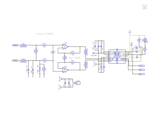
  • I now realize that the common mode input range does not include the isolated DC supply.  Its in the datasheet, but it could be a bit more clear in my opinion.

  • Hi Erik,

    Happy to hear that you were able to identify the issue and thank you for your feedback. Specifically, how could we make the datasheet more clear for you? 

    Most applications do not use a front-end amplifier and tie one of the inputs to HGND, which ensures that the input signal remains within the common-mode input range. However using a front-end amplifier is perfectly acceptable and often assists customers sensing very high currents. We are currently working on a circuit design recommendations document with this front-end opamp configuration and your feedback would be helpful. 

    Do you mind sharing some additional information about your application? 

    What type of signals are you measuring and what are the expected isolation voltage levels? 

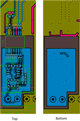
    Looking at your layout, I see that you are using a high side ground plane which is not recommended for applications that will be tested for radiated EMI. Please see this document for additional details: https://www.ti.com/lit/an/sbaa515/sbaa515.pdf

    Additionally, the spacing between the high and low side grounds planes near the connector is quite small. Please ensure that the spacing near the connector near the bottom of the picture is sufficient for the voltage levels in the system. 

  • This application reads a remote galvanic o2 sensor probe, which can be at the end of up to 500' of cable.  The sensor uses around a 2k resistor shunt in the probe to convert current to voltage.  The most critical voltages are from 0-50mV, but the full necessary range is 0-200mV. Offset voltage is rather critical, which either needs to be compensated, or kept low.  For example, at low 02 levels, a 1mV offset can be the difference between a critical and non critical level.

    As to isolation, there is a ground wire that already runs in the cable, so to a certain measure galvanic isolation is more important due to the mechanism of the probe, than needing a specific isolation value.  The old part this is replacing is a AD202JY from AD, which has an isolation value of 750Vrms, 1000V Peak. So while the isolation is a bit narrow, it is somewhat constrained by the connector, which has been working well in past revisions.

    Thank you for mentioning the radiated EMI, I had not seen that particular app note.  About the ground plane, what is your recommendation ?  Better decoupling of the plane, or minimizing it?  In this case I have to supply the op amp somehow.  But I am also concerned about radiating out the cable..

    At the present, I am already using the AMC3301 for this application, and due to the parts shortage and other reasons, I'm updating the board to use the 3336.

    About the datasheet, I guess I naively thought in terms of rail to rail op amps and assumed I needed to shift to center rails.  I think a short sentence in 7.3 noting that vcm is not rail to rail or includes a negative range could be helpful.  Or alternately, perhaps a common mode linearity chart in characteristics.

  • Hi Erik,

    Sounds like an interesting application, thank you for the explanation! 

    From an academic standpoint I would recommend minimizing the high side ground plane if possible. However the 500' of cable is most likely going to be the dominant source of radiation compared to the ground plane. I would recommend adding the ferrite beads that are recommended in the application note as close to the device inputs and HGND as possible to limit the radiation from both the ground plane and the cable. There is a layout example in the application note as well. I have not tested with an opamp on the front end, so I am not sure how this will affect performance. 

    I appreciate the feedback on the datasheet. We will keep this in mind for future revisions.