This thread has been locked.

If you have a related question, please click the "Ask a related question" button in the top right corner. The newly created question will be automatically linked to this question.

AFE5832LP: AFE 5832-LP: Internal Non uniform setup

Genius 9880 points
Part Number: AFE5832LP

Hi Team,

My customer have issue with the device, please see details below for their concern.

I'm having an issue with the TI AFE 5832-LP with the Internal Non uniform setup for the board.

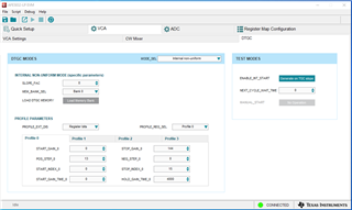
This is the DTGC parameters i have set

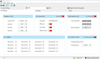
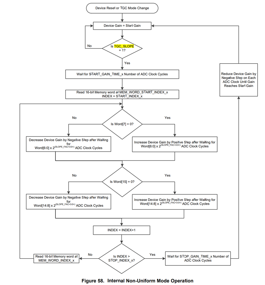
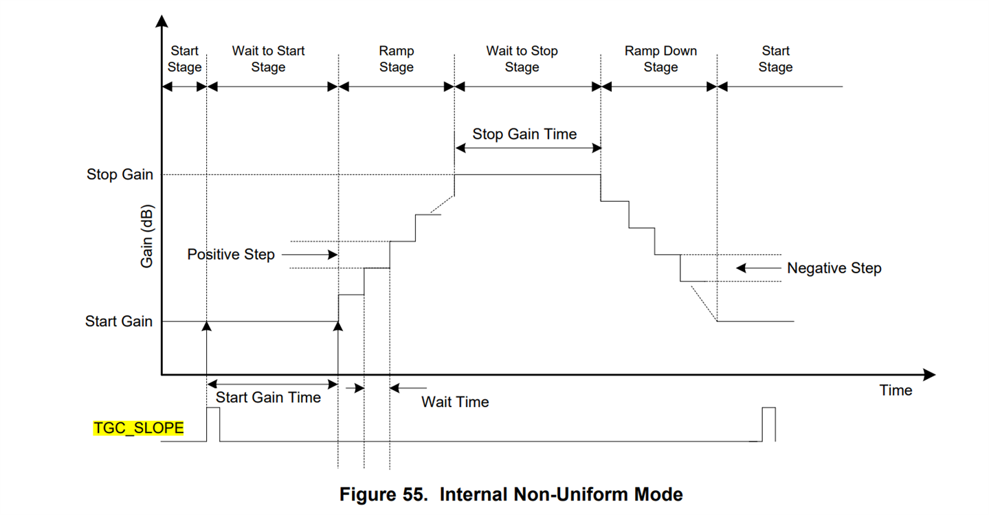
I will explain according to the user manual the signal I have used

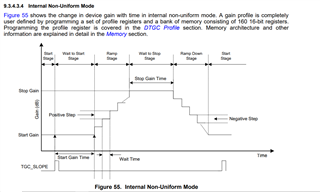
This is the mode i have used in which the TGC_SLOPE signal that was used in TP37 was my signal as seen in the next picture at ch #1

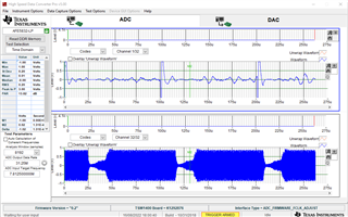
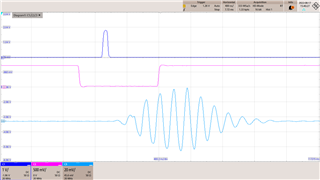
As you can see in channel 1/32 the TGC_SLOPE is accruing every 100uSec slope and the gain as in channel 32/32 is not in SYNC with that signal You can see that also next figure:

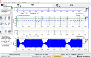
channel 32/32 is not starting at the same location as the pulse in channel 1/32 at times: 0 uSec and 100uSec 200uSec and so on. I would like that the gain will be very low at the points where in CH 1/32 the signal is high (above one volt as you c=vcan see in ch1/32) and if these channels will be in SYNC , then that high voltage will have low gain as you can see in ch32 where the gain have low value

Thank you.

Regards,
May

  • Hi May,

    Thank you for reaching out.

    Firstly, for your information, the TGC_SLOPE signal in the internal non-uniform mode is a level sensitive signal as shown in the flowchart below. 

    When I look at the TGC_SLOPE signal which is AC coupled on Channel 1, I see that the signal is going negative first and then it is going positive, which implies that the TGC_SLOPE signal used for Internal Non Uniform DTGC is actually inverted. It should look like a positive going pulse as shown in the diagram below.  

    If I consider that the TGC_SLOPE is inverted then the device will stay in free running mode because the TGC slope signal will always we high. 

    Can you ask your customer to verify the polarity of the signal, if possible can they share the oscilloscope image of this.

    Also, can you check if they are using the on board CPLD to generate the pulse or giving external signal. If they are giving it externally then please ensure to decouple the CPLD  path accordingly. Figure below shows the snippet of the schematic section. R63 and R72 are the concerned resistors.

    Please let me know if this helps.

    Thanks & regards,

    Abhishek

  • Hi Abhishek,

    Thank you for the information, just received response from my customer ,please see details below.

    My goal is to synchronize the signal as attached in a previous correspondence between CH1 and the beginning of the gain as it appears in CH32

    The signal inserted into TP37 was not the signal in CH1 but a square signal as required which I created from a signal that appears in my system a little before it is the pink signal see attached picture from the scope.

    The signal in dark blue is the signal entered into TP37 as TGC_SLOPE

    Immediately after it, as you can see, the signal is light blue, I want to reduce it as much as possible to a minimum by the TGC, which is activated using TGC_SLOPE

    Thank you.

    Regards,
    May

  • Hi May,

    Thanks for the information.

    From what I could gather is:

    1. Dark Blue signal is the actual TGC_SLOPE signal fed to the ADC

    2. Pink Signal is some other signal fed to Ch-1, can you confirm that this signal is in synchronization with the TGC_SLOPE signal or not?

    3. I could not follow this: Immediately after it, as you can see, the signal is light blue, I want to reduce it as much as possible to a minimum by the TGC, which is activated using TGC_SLOPE. Is it the input signal?

    Also, can you ask the customer to reduce the HOLD_GAIN_TIME_0 from 4000 clks to say 1000 clks and see if they are able to get the synchronized data. Apart from that the settings seems fine.

    If possible, can the customer share the memory bank data they are programming. you can share it on my email - abhishek.vishwa27@ti.com. I will try to bring up the same in the lab and compare my observations. 

    Thanks & regards,

    Abhishek

  • Hi May,

    Also, can you confirm if the TGC SLOPE signal is generated by the customer externally or is being generated by the onboard CPLD. Also, can you confirm the state of registers R72 and R73 if they are mounted or not. If possible can the customer probe the signal going inside the AFE by probing on R73 device end.

    Thanks & regards,
    Abhishek