This thread has been locked.

If you have a related question, please click the "Ask a related question" button in the top right corner. The newly created question will be automatically linked to this question.

ADS1293: ADS1293 noise interference

Part Number: ADS1293

Hello,

We are trying to measure ECG of the human body using ads1293.

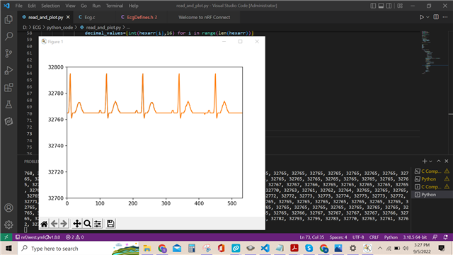
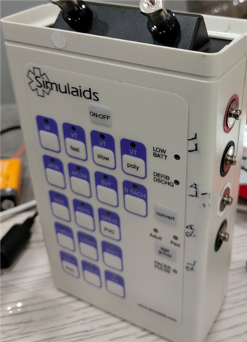
When we connect the electrodes with simulator it works fine as shown in picture.

We are using 5 lead configuration. when using simulator we keep v1 floating.

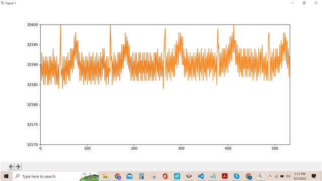
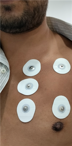
when we connect it with human body using pads, A noise is interfered in the output. 

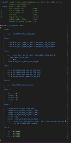
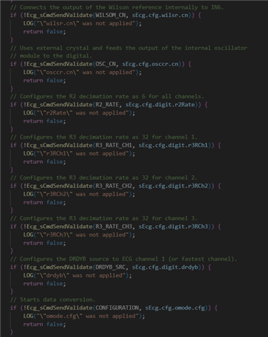
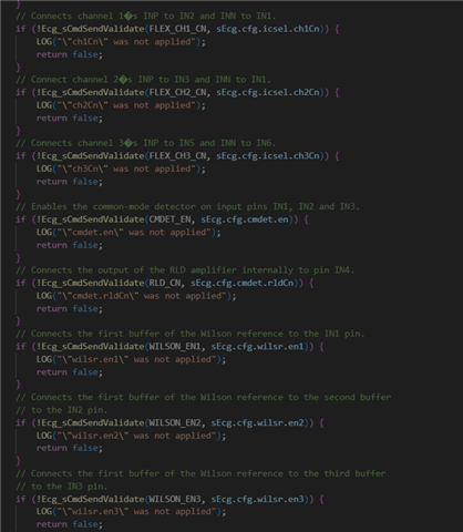
The register setting through code is 

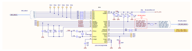
and the schematic is:

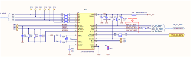
Please guide us what we are doing wrong or what shall be done to avoid this noise. Is there is any configuration of ads1293 that can filter this noise?

Please help us we have been stuck in this for long now.

Regards,

Hussain Rizvi

  • if reading code is difficult, register values that are been configured from code is as below, rest register values are default.

    Register Value Configured:

    0x01      0x11
    0x02      0x19
    0x03      0x2E
    0x0A      0x07
    0x0C      0x04
    0x0D      0x01
    0x0E      0x02
    0x0F      0x03
    0x10      0x01
    0x12      0x04
    0x21      0x04
    0x22      0x20
    0x23      0x20
    0x24      0x20
    0x27      0x08
    0x00      0x01

  • Hi

    May I ask more details and info?

    1. Are you using a ADS1293 evaluation kit/board(EVM) or using your own customized board?

    2. Have you tried using the ADS1293 EVM to acquire ECG signals from an ECG simulator? How was the results and/or noises interference? and note down the desired settings/configuration that give you the results you want?

    3. Have you tried use the RLD?

    You may try different combination settings for datasheet 8.3.11 Common-Mode (CM) Detector and 8.3.11.1 Cable Shield Driving and 8.3.12 Right-Leg Drive (RLD)

    e.g. try different settings for 

    PACE2RLDIN

    8.6.4 Common-Mode Detection and Right-Leg Drive Common-Mode Feedback Control Registers

    CMDET_EN: Common-Mode Detect Enable

    CMDET_CN: Common-Mode Detect Control

    RLD_BW

    RLD_CAPDRIVE

    By the way, very important design and layout notes from data sheet 10 Power Supply Recommendations -

    "

    The CVREF pin requires a 1-µF bypass capacitor-to-ground; this capacitor should have a low ESR and should be placed as close as possible to the pin. The RLDREF pin requires a 0.1-µF ceramic bypass capacitor-toground; this capacitor should be placed as close as possible to the pin.

    A low-ESR bypass capacitor should be placed in close proximity to the CVREF pin. • A bypass capacitor should be placed in close proximity to the RLDREF pin.

    "

    4. Are you designing a 5-lead system? For a 5 lead system, you may take a look of datasheet section 9.2.2 5-Lead ECG Application and note that

    (1) The ideal values of R1, R2 and C1 will vary per system / application; typical values for these components are: R1 = 100 kΩ, R2 = 1 MΩ and C1 = 1.5 nF.

    Thanks

  • Hi, 

    I am greatly pleased for your response. I am not good at electronics but I will try to answer as much as I can.

    1. It's our customized board. The schematic is shared above in the question.

    2. We have used simulator with this customized board not evm. The results are pretty good without any noise. It is also showed above. We used the same configuration for patch attached on the body as shown above and noise can be seen as showed above.

    3. I will try different configurations and will share results with you. We are fulfiling power requirements as shared by you and mentioned on the datasheet.

    4. Yes we are using 5 lead configuration. We have placed R1 = 10k, R2 = 10M and C1 = 1nF

    Thanks.

  • Hi,

    You could also refer to EVM user guide 

    https://www.ti.com/lit/ug/snau138b/snau138b.pdf?ts=1662411139551&ref_url=https%253A%252F%252Fwww.ti.com%252Ftool%252FADS1293EVM

    Section 2.3.2. 5-Lead ECG Application

    Figure 10: 5-Lead Application

    " To see what registers have been changed, click on the “Register Map” icon located on the upper left hand of the GUI"

    Again, the registers I listed earlier might still need to be tried, changed and tested as they could vary/depend on from systems to systems.

    By the way, did you enable any PACE detection and/or Lead-Off detection?  I may suggest turn them off first.

    Also, the noises of your signal seem to be high frequency. 

    You may do a FFT to see/understand what might be the frequency components of the noises/interferences. Which lead or electrode does it appear?

    If needed, you may want to implement either an analog Low Pass Filter or a Digital Low Pass Filter.

    Thanks.

  • Hi,

    We are using customized board which is connect with nrf9160 board and reading serial data from controller through serial. so we cannot run evm application with this board. PCB has been manufactured.

    We will share the result of FFT too.

    By looking at the schematic do you suggest any changes? We are connecting it with electrodes on human body using 5 lead.


    We are configuring only these registers through microcontroller. Rest are as per default.

    0x01      0x11
    0x02      0x19
    0x03      0x2E
    0x0A      0x07
    0x0C      0x04
    0x0D      0x01
    0x0E      0x02
    0x0F      0x03
    0x10      0x01
    0x12      0x04
    0x21      0x04
    0x22      0x20
    0x23      0x20
    0x24      0x20
    0x27      0x08
    0x00      0x01

    With the same configuration, on simulator we are getting results that are very good. It can be seen above in the first question. But as we connect it with electrodes attached to human body noise is integrated in the output. All the screenshots are attached in above first question.

    Please help us in this regard.

    Thanks

  • Hi,

    Do you still have EVM available?

    Have you tried the suggestion mentioned above? Those settings&configurations could vary depend on systems to systems and products to products, so it's not a single solid universal solution for all.

    Have you tried use the RLD? It's very important to use RLD when deal with human subject.

    You may try different combination settings for datasheet 8.3.11 Common-Mode (CM) Detector and 8.3.11.1 Cable Shield Driving and 8.3.12 Right-Leg Drive (RLD)

    e.g. try different settings for 

    PACE2RLDIN

    8.6.4 Common-Mode Detection and Right-Leg Drive Common-Mode Feedback Control Registers

    CMDET_EN: Common-Mode Detect Enable

    CMDET_CN: Common-Mode Detect Control

    RLD_BW

    RLD_CAPDRIVE

    You could also refer to EVM user guide 

    https://www.ti.com/lit/ug/snau138b/snau138b.pdf?ts=1662411139551&ref_url=https%253A%252F%252Fwww.ti.com%252Ftool%252FADS1293EVM

    Section 2.3.2. 5-Lead ECG Application

    Figure 10: 5-Lead Application

    " To see what registers have been changed, click on the “Register Map” icon located on the upper left hand of the GUI"

    Again, the registers I listed earlier might still need to be tried, changed and tested as they could vary/depend on from systems to systems.

    By the way, did you enable any PACE detection and/or Lead-Off detection?  I may suggest turn them off first.

    For schematic, please pay attention to the points mentioned above and also compare with the schematic in the EVM user guide.

    Additionally, you could consider including these parts in the board design to try&test -

    https://www.ti.com/lit/an/sbaa188/sbaa188.pdf

    Cp and Rp, and the 22 k Ohm//47nF and 10 k Ohm//47nF, but be sure to give the flexibility to bypass and/or disable.

    Thanks

  • Hi,
    Since I did not hear back from you, I believe my suggestions answered your questions.
    I will close this post and if you have any pending questions, feel free to post them here or open a new thread.
    Thanks and have a great day!