This thread has been locked.

If you have a related question, please click the "Ask a related question" button in the top right corner. The newly created question will be automatically linked to this question.

ADC12DJ3200EVM: Using external clock to drive the ADC without board modifications

Part Number: ADC12DJ3200EVM
Other Parts Discussed in Thread: LMK04828, , LMX2582

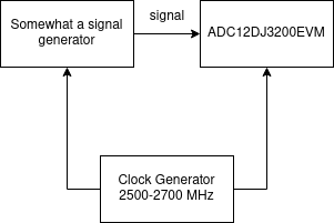
Our system needs to have synced clocks between this ADC and some other part. Ideally, they would share a 2.66 GHz clock for acquisition. I am aware of the possibility to modify the board, but for convenience we want to avoid this. What we are planning to do is feeding this clock signal into CLKIN0 to drive the on-chip clocking (or maybe some lower clock value but synced with the rest of the system). However we don't see a clear solution to this. Following the instructions in page 46, chapter 9.3.5.1 from LMK04828 User Guide Manual, we fed a 1 GHz clock (as a test) into CLKIN0, setting parameter CLin_SEL_MODE to 0 for enabling CLKin0.

However this doesn't seem to work properly. First of all, we would like to know if we are this way of using the device is possible, or if we are understanding it wrongly. Then, we would appreciate some advice on how to execute our needs. If this information matters somehow, the EVM is connected to a ZYNQ+ ultrascale (zcu102).

Thanks,

Alex

  • Hi Alexandr,

    I am looking into this for you.

    Regards,

    Rob

  • Alex, 

    The LMK04828 can generate clocks that are within either of the two integrated VCO limits. VCO0 supports 2370MHz to 2630MHz and VCO1 supports 2920MHz to 3080MHz. The 2660MHz clock for sample clock cannot be generated with the device. This means a 2.66GHz clock needs to be applied to the CLKin1 input of the LMK04828 (this is through the LMK_CLKIN connector J22 on the EVM) and the VCO Mux needs to be set for External VCO on the LMK04828→PLL2 Configuration page.

    What are the other clock frequencies needing to be synced here? Can you put together a quick clocking tree diagram for us?

    Thanks, Chase

  • Thanks for the response. The two devices must be on sync, because otherwise we will acquire incorrect data. I have tried what you suggested, and it does not seem to work. I'm testing it with an RF signal generator, and the ADC is capturing even when I have the generator turned off.

    What I also did is following instructions in page 54, as I believe it's what you are suggesting to me, but this also isn't working. Looks like even with this configuration the ADC is getting a clock from somewhere.

    If you got it running, I would appreciate a config file for the GUI.

    Thank you,

    Alex

  • Alex, I'm sorry but I cannot follow the diagram you have posted. I have some follow up questions to help clarify this on our end.

    • What is the 'somewhat a signal generator' blocks purpose
      • What are the input and output frequencies for it?
      • Why is it connected to the ADC12DJ3200EVM at all?
    • Which device are you wanting the sample clock to come from?
      • External source?
      • using the LMK04828?
      • using the LMX2582?
    • How many EVMs are you trying to synchronize?

    Additionally, the comment I made previously was only to let you know that in order to clock the ADC via the LMK04828 at 2.66GHz, you must use the external VCO mode. If the device sample rate is flexible (2.6GHz for example) this allows more clocking options, is this the case?

    Thanks, Chase

  • I'm sorry for not being clear enough, I can't reveal too much information.

    Basically, the 'somewhat a signal generator' is an RF pulse modulator, it uses the clock from the clock generator to capture an RF signal (yellow wave) and it outputs it as the blue wave. The same clock needs to be fed to the EVM so it captures data ONLY on the peaks, otherwise we will get incorrect data and the reconstruction of the wave will get messed up. As for this, we have matched clock lengths for each device, and we are trying to sync the ADC too.

    I am aware that the ADC chip itself can be driven directly by this clock without LMX and LMK, and that is probably the way we will do this in the final product. But for prototyping purposes, we would like to do this with the EVM as a proof of concept. I hope now I made myself more clear. About your last question, the clock generator has a range of 2.5GHz to 2.7GHz because from device to device there is a variation in frequency (I said 2.66GHz because that is the one we have here).

    I understand that I'm probably asking beyond the capability of these forums and we are already discussing the possibility of modifying the EVM for the external clock source.

    Thank you, Alex

  • HI Alex,

    I will take this offline and send you an email for further discussion.

    Regards,

    Rob