This thread has been locked.

If you have a related question, please click the "Ask a related question" button in the top right corner. The newly created question will be automatically linked to this question.

ADS1298: demodulation phase for the ICG was shifting about 90 deg

Part Number: ADS1298
Other Parts Discussed in Thread: , ADS1296R

Hi Team, 

Good day. I am posting this inquiry on behalf of the customer.

Please see the inquiry below.

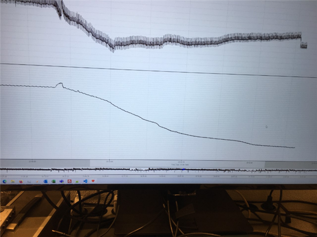
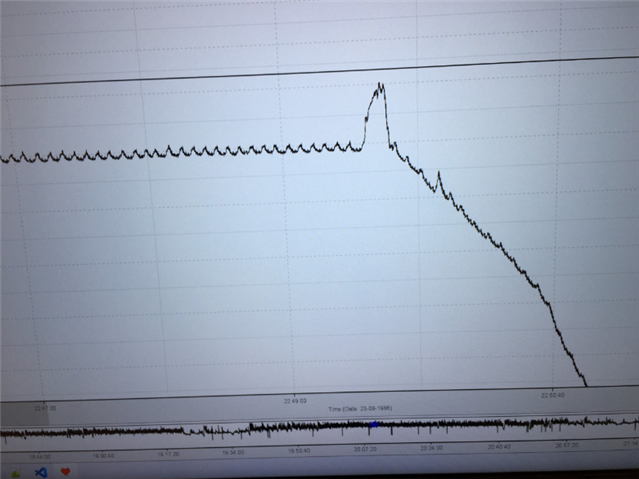
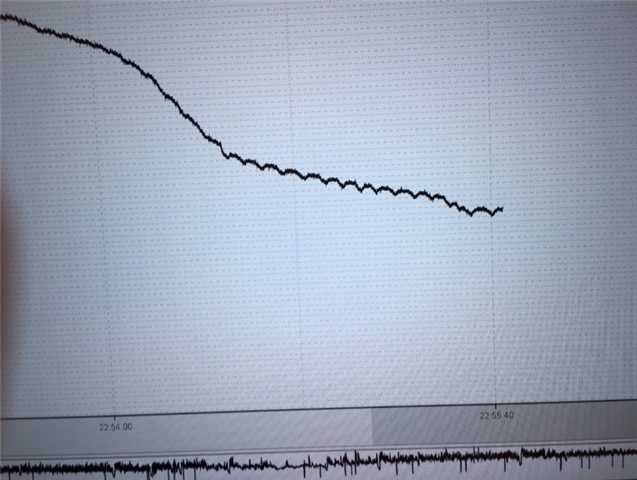
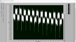
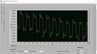
"We discovered a strange effect. It looks like the demodulation phase for the ICG was shifting about 90 deg and not in big steps but very slowly in small steps. I do not think this can happen in the ADS1298R but just to be sure: do you have any comments on this? The signal slowly inverted!"

Thank you for extending your help.

Kind regards, 

Marvin

  • Hi,

    May I ask for further clarification what does customer mean by "demodulation phase for the ICG  was shifting about 90 deg"?

    and also "not in big steps but very slowly in small steps."?

    Could customer provide any plot or screenshot?

    Are they using ADS1298 or ADS1298R?

    Are customer using/trying to detect ECG or RESP signals? And do they happen to have/use a ADS1298 evaluation kit/board(EVM)?

    Thanks

  • Hi Chien, 
    Thank you for your prompt response. Please see the feedback from the customer.
    "Thank you for your response. I will try to answer your question.
    The schematic
    We are you the ADs1298R (or ADS1296R) so with resperation. Because we need more accurate signals (not only resperation but complete ICG) we have an external current source controlled with the RESP_MODP and RESP_MODN outputs. The voltage measurement is done on channel IN1P and IN1N with an instrumentation amplifier and transformer in front. The internal modulator en demod of the ADS129xR is used. With phase setting of 22.5 deg.
    The signals
    This is more difficult to explain so a will show some screenshots. All signals are without any software filtering.
    The first one shows an overview. The top signal is ECG, bottom ICG (Z0).

    The second one is shows the first part
    The third one shows the last part
    So, if you look at the signals you see some change in the shape of the resperation bumps. First they are more like a U in the middle almost gone and in the end more like an upside down U. I believe this can be explained whith a phase shift somewere in the signal path. Possible places for the phase shift:
          -     Current source (but directly controlled through the ADS129xR)
          -     The human body (strange, never seen a big shift like this this before)
          -     The transformer and instrumentation amplifier in combination with the electrodes
          -     The ADS129xR (but is a smooth sift even possible and not only 22.5 deg steps)
    We have seen this problem only once so difficult to measure this. So to rule out the ADS129xR can you give me some advice?"
    Thank you for extending your help.
    Kind regards, 
    Marvin
  • Hi,

    1. I still don't see the explanation/clarification what does ICG mean?

    2. Do they happen to have/use a ADS1298R evaluation kit/board(EVM)? Has customer had/used an evaluation kit/board(EVM) to do the tests they want to do? It's suggested to do the same tests on the EVM board first to understand the proper registers settings and/or hardware configurations before move on to a customer board.

    3. Did customer use an ECG/Respiration simulator to generate the respiration signals? or, What are the signals sources they use to inject the signal? Do they use Right Leg Drive(RLD) pin/electrode?

    4. It's suggested to tackle the problem one-by-one and step-by-step. Can customer capture the ECG signals correctly without using/turning on all other features/functions such as RESP?

    5. Electrodes patches materials, wires/cables and unbalanced/mismatched GND could also affect/introduce the drift and wandering.

    6. Please note very important -

    "When this respiration option is enabled, ADS129xR channel 1 cannot be used to acquire ECG signals. If the RA
    and LA leads are intended to measure respiration and ECG signals, wire the two leads into channel 1 for
    respiration and channel 2 for ECG signals."

    "When respiration mode is
    enabled, channel 1 cannot be used to acquire ECG signals because the internal demodulation circuitry is unique
    to that channel. ECG signals can still be acquired with the same electrodes used for respiration measurement if
    they are also connected to another channel."

    Thanks.

  • Hi Chien,

    Please see the response from our customer.

    1. ICG stands for Impedance CardioGraphy (A noninvasive means of determining cardiac output in which the stroke volume of each cardiac contraction is determined by measuring beat-to-beat changes in the electrical impedance of the chest and neck). Measurement is done using the Internal Respiration Modulator and Demodulator of the ADS129xR. ICG is 'hidden' in the resiration signal. The signal/data I send you did only shows only the respiration and not the ICG. You can see what we do on our website http://www.vu-ams.nl/. This is about the old version hardware
      The VU-AMS can be used to measure: Heart Rate / Inter beat Interval (IBI), Heart Rate Variability (SDNN, RMSSD, IBI power spectrum), Respiratory Sinus Arrhythmia (RSA), Pre-Ejection Period (PEP), Left Ventricular Ejection Time (LVET), Respiration Rate (RR), Stroke Volume (SV) and Cardiac Output (CO), Skin Conductance Level (SCL) and Skin Conductance Responses (SCRs), Tri-axial accelerometry ...
      www.vu-ams.nl
    2. We do use our own board and NOT the evaluation board. It is very difficult to do the same measurements on the evaluation board.
    3. Our signal source is the human body.
    4. ECG signal is perfect.
    5. Drift and wandering is very normal in our application but not a problem at all. It can not explain the inverting of the ICG/Respiration signal
    6. Yes we know. CH1 is for ICG/Respiration, CH2 & 3 for ECG
    So to come back to the my initial question:
    The modulator is modulating the current source (electrodes on the back of the body) using the RESP_MODP & N signals and CH1 is set to use the RESP_DEMOD module for demodulation. Whe use the 32kHz frequency for modulation and a respiration phase of 22.5 deg.
     Because I see the demodulated signal slowly inverting I suspect the phase shift in the body is changed OR the ADS1298R modulator and demodulator changing the demodulation phase.
    But can this happen inside the ADS1298R (without changing its settings?).
    Maybe a nice update for the future: Build a second demodulator inside the ADS1298R with a 90 deg phase shift. In this way you get a vector (Just like a lockin amplifier).
    Thank you for extending your help.
    Kind regards, 
    Marvin
  • Hi Marvin,

    Appreciate for the explanation for ICG - using electrical impedance to correlate/regress/model/estimate the cardiac output.

    ADS129xR's respiration was not designed to make precise&accurate impedance measurement; it was designed to detect whether there is impedance changing with respect to a baseline impedance so there might be some limitation for precise impedance measurement. Customer may refer/take a look of the EVM user guide and use the EVM to see whether the respiration detection meet their ICG applications - by using the EVM and following the user guide, I do see very tiny signal drift(< 0.02mV over 40 seconds), but do not see any inversion -

    Raw data -

    After LPF -

    Are the impedance or baseline impedance customers trying to measure remain steady? note that human body's complex impedance is very complex, non linear and non-homogeneous, so it's not easy to be used for building a good baseline or reference or for calibration.

    E.g. if the simulated respiration frequency changes, the resulting waveform will change too. result or outcome is function of complex impedance and complex frequency, which is not easy to be precisely modeled.

    Customer may consider building a simple RC circuit(e.g. the one on EVM or some ECG simulator also has RESP simulation) or RC network circuits(to very roughly simulate the body impedance) to validate the measurement and observation.

    If customer really wants better accuracy and precise bioimpedance measurement, they may need to consider using constant current source with tetrapolar measurement and in-phase in quadrature filter and do some study/research in bioimpedance measurement.