This thread has been locked.

If you have a related question, please click the "Ask a related question" button in the top right corner. The newly created question will be automatically linked to this question.

ADS1298: 1298 corrpupted channels in daisychain mode (4x)

Part Number: ADS1298

Hi

I have designed my own board with 4 ADS1298 chips. I can read write to registers. I can read out 32 channels. I have attached a signal generator to all channels. 29 out of 32 channels work fine. 3 channels provide some rubbish.

Alle channels and chips are configured the same way.

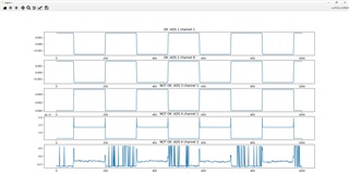
In the plot bleow you see:

Channel 1 Chip 1 And channel 8 chip 2 both looking fine. Allt the other channels look fine. Besides ADS 3 channel 1 , ADS 4 channel 1 and ADS 4 channel 2.

In fact for the plot I used the internal test signal. It is the same if I use a external signal generator!.
And I have the same behaviour on 3 different PCBs ;-(

Any Idea why those 3 channels behave this way?


  • Hi,

    Could you try test the chip 3 and chip 4 one-by-one independently/individually?

    And, please check whether the gain settings and other registers settings are configured the same as the know good/working chips.

    Thanks

  • Hi Chien Chun,

    thanks for the quick reply. Well I thought in daisy chain mode, one can only configure the first chip and has no access to the other chips in the daisy chain. Correct?

  • Hi,

    Yes, you are correct - All devices are configured to the same register values because CS is shared." and "the individual devices cannot be programmed".

    May I ask what data rate do you use? Do you encounter this issue for different data rate? Could you try different rate?

    It's suggested to also follow the data sheet 

    9.4.2.2 Daisy-Chain Configuration

    "Issue one extra SCLK between each data set (see Figure 67)" 

    Note - When daisy chain multiple ADS1298 devices, there are total

    24(status bits)+(8 channels *24 bit)+1(clk/don't care)+

    24(status bits)+(8 channels *24 bit)+1(clk/don't care)+

    24(status bits)+(8 channels *24 bit)+1(clk/don't care)+

    .

    .

    .

    and

    page 58.

    In the case if you need to break the daisy chain temporarily and test individually/indecently. Not knowing how the PCBA(s) were designed, is there still a way to pull/write the DAISY_IN to low or GND, and only connect the DOUT of the problem chip to your master/host? 

    If individual chip works fine independently, then it's suggested to probe the /CS, /DRDY, SCLK, DAISY_IN and DOUT lines to check whether SCLK clocks/latches each DOUT bit properly.

    Thanks

  • solved it. I had a bug in my code when taking care of the one extra clock cycle.