This thread has been locked.

If you have a related question, please click the "Ask a related question" button in the top right corner. The newly created question will be automatically linked to this question.

ADS1298R: Augmented leads in analog domain

Part Number: ADS1298R
Other Parts Discussed in Thread: ADS1298,

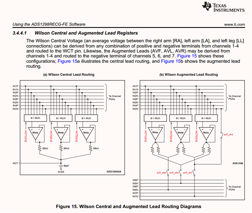
Section 9.3.1.7.3.1 Augmented Leads of the datasheet says: In a typical implementation of the 12-lead ECG with eight channels, the augmented leads are calculated digitally. In certain applications, it may be required that all leads are derived in analog rather than digital.

Assume that my requirement is to have the augmented leads acquired in analog domain. If I understand the description correctly, I'd have to do the following:

  • connect the limb leads as following:
    • IN2N - RA (R)
    • IN2P - LA (L)
    • IN3N - RA (R)
    • IN3P - LL (F)
  • configure WCT amplifiers as following:
    • WCTaA - connected to IN2N - RA (R) (011 in WCTA field of WCT1 register)
    • WCTaB - connected to IN2P - LA (L) (010 in WCTB field of WCT2 register)
    • WCTaC - connected to IN3P - LL (F) (100 in WCTC field of WCT2 register)
    • enable the amplifiers on aVF_CH6, aVL_CH5, and aVR_CH7 and disable on aVR_CH4 (1110 in the oldest 4 bits of WCT1 register)
  • connect the limb leads again to channels 5, 6, and 7 as following:
    • IN5P - LA (L) - since IN5N is (R+F) / 2
    • IN6P - LL (F) - since IN6N is (R+L) / 2
    • IN7P - RA (R) - since IN7N is (L+F) / 2

Is this correct?

And what should I do with the IN5N, IN6N, and IN7N inputs?

Thank you in advance.

Mike

  • Hi,

    May I ask if you happen to have/use an evaluation kit/board(EVM)?

    You may take a look of the EVM user guide 

    https://www.ti.com/lit/ug/sbau181b/sbau181b.pdf?ts=1666212891762&ref_url=https%253A%252F%252Fwww.google.com%252F

    page 38 and search for WCT for the electrodes - pins connection.

    Also, in the end of the EVM user guide, there are EVM's schematics that can be used as V leads reference design or for test&evaluation.

    Thanks

  • Hi ChienChun,

    Yes, I'm using the EVM. What I can read in the EVM user guide in section 4.6 Lead Derivation is: The EVM is configured to generate the 12 ECG signals using 10 electrodes connected to the eight ADC channels. Lead I, Lead II, and V1-V6 are computed in the analog domain, while the augmented leads and Lead III are computed digitally.

    My question concerns the situation where I want to have all leads derived in analog domain, and not digital.

    The document mentioned by you, in section 3.4.4.1 Wilson Central and Augmented Lead Registers (page 22), says something about routing the augmented leads. If I understand it correctly, negative inputs of channels 5, 6, and 7 are internally connected to (R+F) / 2, (R+L) / 2, and (L+F) / 2 respectively (if Wcta, Wctb, and Wctc are muxed to R, L, and F respectively). And my question is which signals do I need to connect to physical positive and negative inputs of channels 5, 6, and 7 to have the augmented leads measured in analog domain?

  • Hi,

    If you want all 12 ECG leads to be acquired in analog, you will need two ADS1298(R) chips.

    There are different options and approaches, Refer to EVM user guide 3.4.4.1 Wilson Central and Augmented Lead Registers and 4.6 Lead Derivation.

    One could use one chip's 2 channels to acquire 2 primary leads(from 3 electrodes already) and uses these 2 primary leads(from 3 electrodes already) to create the WCT and acquire V1~V6 as shown in the EVM's schematic.

    Then, for Augmented Lead, one could use another ADS1298 and refer to datasheet 9.3.1.7.3.1 Augmented Leads or EVM user guide (b) Wilson Augmented Lead Routing, to connect RA, LA, LL to any 3 of INxP to INxN(NOTE: x right here can only be channel 1~4), and then use the WCT1 and WCT2 8:1 MUXes to select the 3 pins connected to RA, LA, LL to generate the summation of any two electrodes divided by two -

    e.g.

    avF_ch5=(LL+LA)/2,

    avF_ch6=(LL+RA)/2,

    avF_ch7=(LA+RA)/2,

    depending how the electrodes to pins connection and the WCT1 and WCT2 muxes setting.

    And then, these three augment references are internally fetched into 

    IN5N, 

    IN6N,

    IN7N.

    Then, one can connect

    RA to IN5P,

    LA to IN6P,

    LL to IN7P    

    This way, 

    Ch5 = RA - (LL+LA)/2 = aVR

    Ch6 = LA - (LL+RA)/2 = aVL

    Ch7 = LL - (LA+RA)/2 = aVF

    Feel free to take a look of these thread-

    https://e2e.ti.com/support/data-converters-group/data-converters/f/data-converters-forum/700810/ads1298-augmented-leads

    Thanks

  • Hi ChienChun,

    Thank you for your answer. It doesn't fully answer my question, though.

    If you want all 12 ECG leads to be acquired in analog, you will need two ADS1298(R) chips.

    I understand that, it's not answering my question.

    There are different options and approaches, Refer to EVM user guide 3.4.4.1 Wilson Central and Augmented Lead Registers and 4.6 Lead Derivation.

    I've checked those references several times, they don't provide any answer to my question.

    One could use one chip's 2 channels to acquire 2 primary leads(from 3 electrodes already) and uses these 2 primary leads(from 3 electrodes already) to create the WCT and acquire V1~V6 as shown in the EVM's schematic.

    It's clear to me, I use the first chip to measure I, II, V1-V6. It doesn't answer my question.

    Then, for Augmented Lead, one could use another ADS1298 and refer to datasheet 9.3.1.7.3.1 Augmented Leads or EVM user guide (b) Wilson Augmented Lead Routing, to connect RA, LA, LL to any 3 of INxP to INxN(NOTE: x right here can only be channel 1~4), and then use the WCT1 and WCT2 8:1 MUXes to select the 3 pins connected to RA, LA, LL to generate the summation of any two electrodes divided by two -

    e.g.

    avF_ch5=(LL+LA)/2,

    avF_ch6=(LL+RA)/2,

    avF_ch7=(LA+RA)/2,

    depending how the electrodes to pins connection and the WCT1 and WCT2 muxes setting.

    I understand that, it's actually what I have written in my initial post and what I have read in the datasheet of ADS1298R. It still doesn't answer my question.

    This way, 

    Ch5 = RA - (LL+LA)/2 = aVR

    Ch6 = LA - (LL+RA)/2 = aVL

    Ch7 = LL - (LA+RA)/2 = aVF

    I understand that, that's what I have written in my initial post. It doesn't answer my question.

    I started with that post, I couldn't find an answer to my question there, that's why I started a new thread.

    My question is:

    what do I physically do with IN5N, IN6N, and IN7N inputs of the chip?

    Do I leave them floating? Do I connect them to the ground? Do I bias them with any voltage and if yes, which? The quoted document's do not say anything about it. And from the schematics I conclude I should leave them floating (N/C) but it's not a proper practice from the EMC point of view, as long as I know.

    I'd really appreciate if you can simply tell me what should be done with the IN5N, IN6N, and IN7N inputs on the board. 

    Thank you.

  • Hi,

    If you are trying to design/layout an customer PCB, one could design those, e.g. IN5N, IN6N and IN7N, the same way shown in the EVM user guide schematic; however, it's suggested to use the EVM to evaluate first.

    Thanks

  • Hi ChienChun Yang,

    With your every message I get the impression that we speak different languages. 

    As far as I'm concerned, the EVM guide does not say what to do with IN5N, IN6N, and IN7N pins when using the WCT amplifiers for internal routing of the augmented leads for the analog domain.

    All I could find, concerning the routing, is the following:

    First of all - it does not say how to externally route the IN5N, IN6N and IN7N input pins. Looking at the diagram I would leave them floating but I want to be sure, hence my question.

    Another question that gets into my mind - is it possible to drive the WCT pin and augmented leads references (IN5N, IN6N and IN7N) internally within one chip at the same time?

    From what you said earlier, it's not possible:

    One could use one chip's 2 channels to acquire 2 primary leads(from 3 electrodes already) and uses these 2 primary leads(from 3 electrodes already) to create the WCT and acquire V1~V6 as shown in the EVM's schematic.

    Then, for Augmented Lead, one could use another ADS1298 and refer to datasheet 9.3.1.7.3.1 Augmented Leads or EVM user guide (b) Wilson Augmented Lead Routing, to connect RA, LA, LL to any 3 of INxP to INxN(NOTE: x right here can only be channel 1~4), and then use the WCT1 and WCT2 8:1 MUXes to select the 3 pins connected to RA, LA, LL to generate the summation of any two electrodes divided by two

    So like the first chip measures I, II, creates WCT and measures V1-V6 and the second chip measures I, II, and measures augmented leads. But then, for the second chip do the IN5N, IN6N and IN7N pins are left floating, must be grounded, biased?

    I'm trying to evaluate the EVM but I have the questions stated above and those are answered neither in user guide of the EVM nor in the datasheet of ADS1298R.

  • Hi,

    I agree that the datasheet and EVM user guide do not explicitly state and mention the points you are asking in a step-by-step manner, and unfortunately that's how they were developed and written.

    So, it's suggested to use the EVM to test out the ideas, concepts and configurations to verify and/or validate.

    Please check the schematic part at the end of the EVM user guide, e.g. page 62 and 63, to see how the IN5N, IN6N and IN7N are designed. It's suggested to start with that reference design first, e.g. IN5N, IN6N and IN7N are not grounded nor biased in the schematic. Customer can use the EVM to configure to the lead configurations they have in mind to test and get ideas, e.g. configure the EVM to the augmented leads and use GUI to look at the signals.

    And, according to the data sheet, for all analog 12 lead system, "more than eight channels are used to generate the standard 12 leads."

  • Hi ChienChun Yang,

    Thank you. 

    I agree that the datasheet and EVM user guide do not explicitly state and mention the points you are asking in a step-by-step manner, and unfortunately that's how they were developed and written.

    If it was stated there I wouldn't have to ask questions, right?

    I know how the EVM is designed. We did evaluate the EVM and our goal is to design an ECG device where all limb leads (i.e. I, II, III, aVR, aVL, and aVF) are measured in analog domain together with respiration
    Using EVM produces terrible level of noise, that's why the next step is to develop a prototype PCB in hope to reduce that noise. That's why I need to know how to handle the physical pins of IN5N, IN6N, and IN7N. Studying the diagrams provided I understand that those should be left floating because, in the configuration as in Figure15b they are directly connected to the outputs of the WCT amplifiers. But leaving them floating is contra-intuitive from the EMC point of view. Hence my initial question that still remains unanswered.

    I'd really appreciate an official statement of TI in this aspect.

    Thank you in advance.

  • Hi,

    Thanks for providing further detail information - "Using EVM produces terrible level of noise, ... ", which was not mentioned.

    If this is the case, you may want to start looking from there to understand/figure out the causes and/or workaround before altering or changing anything or go to a board design.


    Would you mind sharing any registers settings screenshots and the signals you acquired?

    Do the noises appear in all the channels or just certain channels?

    What might be the noises sources, frequencies, and amplitude?

    Sometimes the noises may not be from the EVM, it could be from the surroundings, and/or the electrodes/patches materials, wires/cables used and/or from the PC, computers, adapters, etc.

    Have you tried the internal test signals to see whether the noises exist?

    One important note from the data sheet - 

    "When this respiration option is enabled, ADS129xR channel 1 cannot be used to acquire ECG signals. If the RA and LA leads are intended to measure respiration and ECG signals, wire the two leads into channel 1 for respiration and channel 2 for ECG signals."

    "

    The respiration measurement circuitry on the ADS129xR employs out-of-band amplitude modulation and demodulation to measure changes in thoracic impedance that correspond to breathing. When respiration mode is enabled, channel 1 cannot be used to acquire ECG signals because the internal demodulation circuitry is unique to that channel. ECG signals can still be acquired with the same electrodes used for respiration measurement if they are also connected to another channel.

    "

    Do you happen to have/use an ECG simulator? and Do you use RLD?

    In the meantime, I will escalate/ask other engineers regarding to the IN5N, IN6N, and IN7N pins connection question and get back to you asap. 

    Thanks

  • Hi,

    After discussing with other engineer internally, it's still suggested to leave IN5N, IN6N, and IN7N pins floating externally if not used externally.

    Section 9.2 Functional Block Diagram and Figure 25 show there are EMI filter right after each input pins.

    Also, these are slow speed analog signals, which should not cause impedance/signal bounce/reflection issues.

    Thanks.

  • Thank you, I'll keep to this suggestion when designing the PCB.