This thread has been locked.

If you have a related question, please click the "Ask a related question" button in the top right corner. The newly created question will be automatically linked to this question.

ADS8861: Adjusting offset of ADC

Part Number: ADS8861
Other Parts Discussed in Thread: ADS8860,

Hi Team,

Can you please help us with our customer's inquiry below?

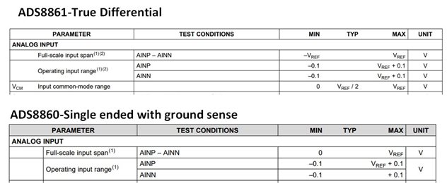
We are using the ADS8860 in an existing design.  I want to add an offset to the AIN pin.  the datasheet says that I need to keep that at ground between +/- 0.1V. An FAE told me that I could swap from the ADS8860  to the ADS8861 and then have a larger signal on AIN. However, these parts share a datasheet, and I don't see anything in there indicating that I can move AIN off of +/-0.1V from ground for any part in that family.

My signal into the AIP pin swings from 1.6V to 2.6V. Purpose of query is that I want to put a 1.5V signal on the AIN pin to remove that offset. Can it be achieved with ADS8861?

Regards,

Danilo

  • Danilo,

    1. The ADS8860 is a single ended device with ground sense.  Normally on this device the negative input is connected directly to ground, but the ground potential can be sensed remotely and slightly different than the device ground.  
    2. The ADS8861 is a true differential input device.  That means that either input can be connected to any voltage from -0.1V to Vref+0.1V, and the device will measure the difference between AINP and AINN.  
    3. See the key specifications that differentiate the two devices listed below.
    4. To directly answer your question, the ADS8861 will allow you to connect 1.5V to AINN and apply your signal (1.6V to 2.6V) to AINP.  It will subtract the two signals AINP - AINN.  I don't think that this will necessary yield better accuracy than using the ADS8860 and mathematically subtracting the 1.5V.  Nevertheless, it is possible to do this.
    5. ADC-Input-types-Video explains the difference between single ended, differential, and true differential.

    Let me know if you have further questions. 

    Art

  • Thanks Art.

    A couple of follow-up points:  1.  Where did you find thes tables?  I looked all over the ADS886X datasheet and did not see it.

    2.  Accuracy isn't the issue that I am trying to solve.  Right now, with no input our to our device and due to the existing bias on our device, it looks like the ADC is reporting a half-rail input.  Adding this voltage to AIN is just masking an effort to mask another problem.

    I appreciate the help.

  • Ivan,

    1.  I suspect that you may have an old data sheet.  I do not see an ads886x data sheet, but two separate data sheets for the two version.  

    http://www.ti.com/lit/gpn/ads8860 - top of page 6.

    http://www.ti.com/lit/gpn/ads8861 - top of page 3

    2.  I'm not sure that I fully understand the issue you are masking, but if you want to make the differential measurement, the ADS8861 should work for you.

    Best regards,

    Art