This thread has been locked.

If you have a related question, please click the "Ask a related question" button in the top right corner. The newly created question will be automatically linked to this question.

DAC8551: DAC8551 output wrong value after running a while.

Part Number: DAC8551

I have some instances of DAC8551 that output is 2V instead of 5V.

VDD is 5Vdc, Vref is 5Vdc. 

When I output 65535 with 24bit , it works fine at the beginning. After some use, some boards are giving me 2Vdc output instead of 5V. 

Wonder if the chip is bad or my timing is off. 

{

AT91F_PIO_SetOutput(PORT_DAC, DAC_CS);
AT91F_PIO_SetOutput(PORT_DAC, DAC_CS_LASER_TEC);
__disable_irq();

AT91F_PIO_ClearOutput(PORT_DAC, DAC_CS_LASER_TEC);
write_dac(dac_value);
__enable_irq();

delay_us(2);
AT91F_PIO_SetOutput(PORT_DAC, DAC_CS_LASER_TEC);

}

#define DELAY2 1
void write_dac(unsigned short dac_value)
{
unsigned int dummy;
unsigned int value1;

value1 = dac_value;


AT91F_PIO_SetOutput(PORT_DAC, DAC_CLK);
AT91F_PIO_ClearOutput(PORT_DAC, DAC_DIN);


for (dummy = 0; dummy < 24; dummy++)
{
unsigned short temp;
temp = 1 << (23 - dummy);
if (temp & value1)
AT91F_PIO_SetOutput(PORT_DAC, DAC_DIN);
else
AT91F_PIO_ClearOutput(PORT_DAC, DAC_DIN);
AT91F_PIO_ClearOutput(PORT_DAC, DAC_CLK);
AT91F_PIO_SetOutput(PORT_DAC, DAC_CLK);
}

  • Hi Andrew, 

    I assume you are using the same code with the working boards and non working boards. Is that right?

    Can you share a schematic and a oscilloscope screenshot of the write sequence on one of the working boards and one of the non working boards? Is the voltage really 2V? Or closer to 2.5V? 

    Best,

    Katlynne Jones  

  • All the boards and code are the same. 

    2V is just one symptom, I have seen symptoms where output results becomes unstable, value all over the place. Also, value do not change anymore with new updates. 

    I had to replace the chip with a new DAC8551 on it and it worked again.  

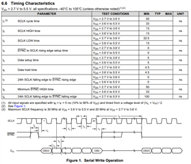
    What do I need to watch out for oscilloscope debugging? Any timing requirements I need to meet?

  • Hi Andrew,

    You should ideally be meeting all of the timing requirements in the datasheet. You can post the screenshot here so I can take a look and let you know if anything looks concerning. just make sure it is zoomed in enough to see the individual clock edges. Please include the SCLK, SYNC, and DIN signals. Also make sure the correct SPI mode is being used. The clock polarity can idle high or low, the clock phase needs to be set to the data is changed on the rising edge and captured on the falling edge. The oscilloscope shot might also show noise that is corrupting the write sequence. 

    It will also be helpful if I can review the schematic. There could be something in your design causing the parts to be damaged. This would make sense if you're saying replacing the part solves the issue. Are there any boards that have never shown an issue? 

    Best,

    Katlynne Jones 

  • Found an issue in the schematics.