This thread has been locked.

If you have a related question, please click the "Ask a related question" button in the top right corner. The newly created question will be automatically linked to this question.

ADS8671: ADS8671 polling speed

Part Number: ADS8671
Other Parts Discussed in Thread: OPA320

I'm trying to count random pulses that cross a negative trigger threshold of -55 mV for only about 25-50 microseconds.  The ADS8671 is almost working but it's occasionally skipping pulses.

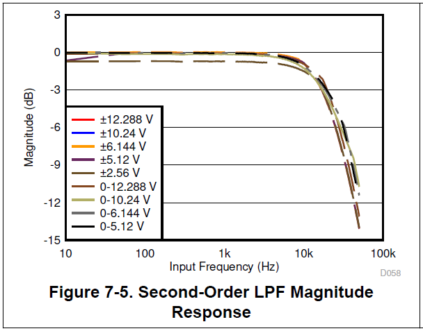
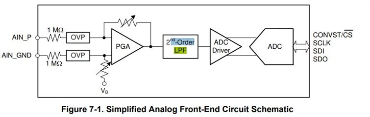
I think the problem is due to the 15 kHz Low-Pass filter in front of the detector, since 15 kHz -> 66 microseconds.  Is there a way to speed up the ADC so I don't lose pulses?  Would modifying the decoupling capacitor between REFIO and REFGND help or is there a better approach?

  • Hi H. Williams,

    If you are running the ADS8671 at 1MSPS, there really isn't any way to make it sample faster.  How often do these pulses occur?  What is the purpose of the 15kHz filter?  Can you provide a schematic or maybe some scope traces that show the pulse train and the relevant control signals to the ADS8671?

  • The pulses occur randomly.  On average, they occur every 100 milliseconds.  

    The LPF is built-in to the ADS8671.  Figure 7.1 in the datasheet shows the 2nd order LPF is located between the PGA and the ADC driver: Simpolified Analog Front-End Circuitafter the 

    From ADS8671 datasheet:

    7.3.5 Second-Order, Low-Pass Filter (LPF) In order to mitigate the noise of the front-end amplifier and gain resistors of the PGA, the AFE circuit of the device features a second-order, antialiasing LPF at the output of the PGA. The magnitude and phase response of the analog antialiasing filter are shown in Figure 7-5 and Figure 7-6, respectively. For maximum performance, the –3-dB cutoff frequency for the antialiasing filter is typically set to 15 kHz. The performance of the filter is consistent across all input ranges supported by the ADC.

    Here's the schematic for my breakout board:

    Schematic

  • Doah!

    I was not thinking about the internal LPF, sorry about that!  Can you share a plot or something that shows the input pulse train versus the conversion results Also, how do you have AGND and DGND referred to each other?

  • AGND and DGND are connected to the same ground rail.  Here is a picture of my breakout board connected to a Teensy 4.0 microcontroller which displays the count on an OLED.  The bottom breadboard has an nRF5280 generating test pulses.  After 10,000 pulses the ADS8671 only shows 9,954.  I verified the count using the totalizer on my oscilloscope.  The pinout of my custom breadboard for the ADS8671 uses the same pinout as the chip.

    Counter test

  • How fast are you actually running the ADS8671 in this setup?  With these fly wires, you may have some signal integrity problems that are causing the difference in the pulse count.

  • Not sure I know what you mean by how fast.  The SPI baud rate is 18 MHz.  However, I'm not using SPI to count.  Instead, I'm using SPI to set up an alarm threshold and afterwards I'm using the microcontroller GPIO pin to count the pulses on the ADS8671 alarm pin (14).

    I think we're getting a little off topic on this question.  I just want to know the best way to modify the frequency of the LPF. I don't fully understand section 7.3.5 of the datasheet (included in my prior post).  I think the LPF is causing a bottleneck that at 15 kHz is limiting the ADC sample rate to approximately 66 microsecond windows.  Ideally, I think I would need to boost the speed to at least 40 kHz to decrease the window to 25 microseconds (the length of my shortest pulses).

    The following section of the datasheet implies that LPF frequency can be adjusted.  I'd really appreciate some advice on best practices for modifying the LPF frequency and a confirmation that I'm understanding the datasheet correctly..

    7.3.7.1 Internal Reference
    The device features an internal reference source with a nominal output value of 4.096 V. In order to select the internal reference, the INTREF_DIS bit of the RANGE_SEL_REG register must be programmed to logic 0. When the internal reference is used, the REFIO pin becomes an output with the internal reference value. A 4.7-μF (minimum) decoupling capacitor is recommended to be placed between the REFIO pin and REFGND, as shown in Figure 7-7. The capacitor must be placed as close to the REFIO pin as possible. The output impedance of the internal band-gap circuit creates a low-pass filter with this capacitor to band-limit the noise of the reference. The use of a smaller capacitor value allows higher reference noise in the system that can potentially degrade SNR and SINAD performance. The REFIO pin must not be used to drive external ac or dc loads because of limited current output capability. The REFIO pin can be used as a source if followed by a suitable op amp buffer (such as the OPA320).

  • The ADS8671 can run at 1MSPS throughput.  That means taking 1 sample every 1uS which includes doing the actual conversion and then piping the data back to the microcontroller through an SPI interface.  If you have a 25-50uS pulse every ~100 mS or so, there's no good reason I can think of that you would be missing any pulses - even with the 15kH LPF, you should get most of the signal into the ADC.  Are you not actually reading the ADC data but just looking at the alarm pin?  There is no way to modify the internal LFP, it's fixed.  Section 7.3.7.1 is referring to the noise that can be introduced on the reference, which is going to determine the overall accuracy of the conversion result.  While not shown in the simplified Analog Front End above, it would be connected with the ADC, and not the LPF block.  If all you are doing is setting up the ADC trigger threshold and then counting the ALARM pulses, would a simple comparator work for that? 

  • Thanks for your detailed response; it is very helpful!  I think I understand.  Is it fair to say that the ADS8671 is capable of measuring 1 million samples per second but it is only accurate up to 15,000 samples per second because after 15,000 the noise increases exponentially based on Figure 7.5?

    Figure 7.5

    Currently I'm just trying to make sure all pulses are counted.  I figured the alarm pin would be the fastest approach.  I do eventually want to measure the voltage of the pulses that range from about  -45 mV to -200mV.  There is about +/-25 mV of background noise.  Will the additional noise introduced at higher sampling rates prevent this type of accuracy?  Moreover how many bits will the noise skew the results at the necessary sampling rate?

  • Hi Hugh,

    No - not quite fair to say that.  The ADS8671 can accurately convert the the input signal at 1 MSPS, so there are no issues there as far as the ADC is concerned.  The 15 kHz bandwidth is just going to attenuate your signal a bit, so depending on where you have the limits set and the magnitude of the pulse - you might or might not 'trip' the Alarm pin.  You might try reducing the alarm limit to be something less than the expected conversion result for the -45mV level for starters.  Not sure where your +/-25 mV of noise comes from, but if you really were sampling at 1MSPS and plotting out the actual conversion results, I'm fairly certain that you would see a series of what looks like 'inverted' shark fins (due to the 15K LPF) with varying magnitude (based on -45 to -200 mV levels) swimming through a sea of data.

  • Is there a way to calculate the loss of resolution as the sampling rate increases?

  • What do you have the alarm threshold set for now?  As I mentioned earlier, the 15k LPF is going to have an impact on the DVDT of your pulse.  If you have any sort of analog spice simulator tool handy (try TINA-TI or PSPICE-FOR-TI if you don't) that you can model the pulse through a LPF, you can see what the actual input to the ADC inside the ADS8671 will get on its input.  If you knew when the pulse was coming along, you could adjust the acquisition time of the ADS8671 to sample longer and get potentially an accurate peak value for the pulse waveform.  If the pulses are truly coming at random intervals and variable pulse widths, the best thing to do would be to sample at the 1MSPS rate and then you would be able to reconstruct the pulse as it appeared on the ADC input.  In the end, you should not loose resolution of the pulse train at higher sampling rates - it should actually get better.