This thread has been locked.

If you have a related question, please click the "Ask a related question" button in the top right corner. The newly created question will be automatically linked to this question.

ADS1291: Device returning 0 values after initialization

Part Number: ADS1291

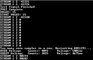
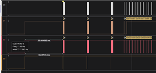
I'm currently working with an ADS1291, and verifying that it can generate test signals, as well as read signals passed in. Currently, I'm occasionally getting back 0 responses when reading the ID register, when reading back the configuration settings, and when reading data after a data ready signal is received.

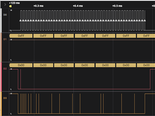
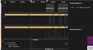
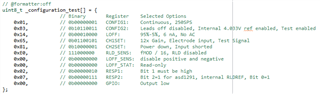
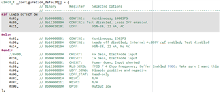
It's more often than not that I receive these issues, but most of the time, I'm able to successfully write and read back the test signal configuration. Even if I read back an ID value of 0 afterwards however, it's still able to generate the test signal. Once the test signal has been fully processed, I try to write the normal operating configuration, and it usually fails by sending back 0 somewhere in the process. I've included images of my configurations below. 


My configuration changing process is as follows:

1. Wait 4096 TMOD cycles after startup (31,998uS)
2. Set RESET high and wait 1 second
3. Set RESET low and wait 1 TMOD cycle (8uS)
4. Set RESET high again and wait 18TCLK cycles (36uS)
5. Send SDATAC command
6. Write 0xA0 to CONFIG2 for PDB_REFBUF
7. Wait until VREFP reaches at least 2.2V
9. Write 11 bytes of config to CONFIG1 register
10. Wait 18 TCLK cycles (36uS)
11. Read back config register and verify it matches the config passed in
12. Read ID register and verify it matches expected value of 0x52s
13. Send START command
14. Send RDATAC command

It seems as though most of the time it sets the configuration for the test signal properly, but it's not surefire. It's seemingly random where it fails when changing to _configuration_default, but most of the time either reads a 0 back when verifying the configuration, a 0 back when verifying the ID, or a stream of 0s triggered by the data ready pin. 

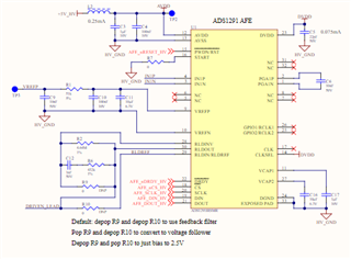
Our SPI is currently set to CPOL0 CPHA1 and 500kHz transmission rate, and this is the hardware configuration we're currently using in case that helps. 

  • Hi,

    Is this the first time you encounter this?

    When do you get the chip?

    Do you always read 0 back from the ID: ID Control Register (Factory-Programmed, Read-Only) (address = 00h)?

    Could you take a look/picture of the ADS1x91 top surface and let me know what it reads?

    ----------------------------------------------------------------------------------------------

    May I ask what you mean "occasionally"? Does it mean sometime it reads 0 and sometimes other values?  What value? 

    ------------------------------------------------------------------------------

    For, "Once the test signal has been fully processed, I try to write the normal operating configuration, and it usually fails by sending back 0 somewhere in the process. "

    Could you explain a bit more on "it usually fails by sending back 0 "?   Are you saying all the registers reading?

    Did you send any RESET command in between?

    Could you also double check your /RESET pin to make sure it was not accidently pulled low in between?

    ---------------------------------------

    For, "3. Set RESET low and wait 1 TMOD cycle (8uS)"

    Are you trying to RESET here?

    Please note- " It takes 9 fMOD cycles to execute the RESET command. Avoid sending any commands during this time."

    -----------------------------

    What is the DVDD voltage? make sure the SPI's SCLK  meet the  tSCLK SCLK period  in datasheet section 6.6.

    Thanks

    Thanks

  • DVDD is currently being powered by 3.3V, and the SCLK period is 6uS. 

    I set the reset signal low for 8uS, but then set it high and wait for an additional 18TCLK cycles or 36uS before sending any other commands. I didn't see the note about 9 fMOD cycles before, and I was basing the 18 TCLK cycles on the section 10.1 Power Up Sequencing. I just changes the wait period after setting RESET high after pulsing it low to 71uS for 9 fMOD cycles, as well as to 36uS to include the 9fMOD cycles, as well as the 18 TCLK cycles mentioned in section 10.1, but unfortunately I still receive the same result. 

    I'm not always reading back 0 from the ID register, or any these registers, but once I start reading 0 it only seems to send 0s.
      
    In this image, D0 is AFE_SCLK_HV, D1 is AFE_DIN_HV, D2 is AFE_DOUT_HV, and D3 is AFE_nCS_HV from the schematic. As shown, it seems like the data line is pulsing low as if it's valid data, but it's only 0 no matter what. This seems to usually happen just after writing a new configuration as shown below. 


    In this case, the test signal passed its configuration, but once the default configuration was switched to, it was able to verify the read and write process of the configuration register with memcmp, but once SDATAC was sent, the data read in was continuously 0. Sometimes it will instead read 0 when trying to read the configuration register to verify the write went properly, and sometimes it will read 0 when verifying the ID register is the right value after changing the configuration. When it doesn't return 0s, the values are the expected values for all registers. 

    The top of the chip also reads 
    ADS
    1291
    TI 241
    C6T5 
    However, I don't believe the failure to return the proper ID value is related to the part number.

    I have verified that the reset is only being pulsed low before these configuration writes, and it is pulsing low for 14uS, and waiting for 141uS before writing the configuration request.The images below show AFE_nRESET_HV on D3.

    It's also strange that it seems to be fairly consistent that it almost always fails the first 2 configuration writes before getting set and verified the 3rd time. The example below shows the startup process with 2 failed configuration writes, then a successful configuration write, but after the test signal is set to be generated, in this case we just got regular 0 samples instead.