This thread has been locked.

If you have a related question, please click the "Ask a related question" button in the top right corner. The newly created question will be automatically linked to this question.

ADS1298RECGFE-PDK: What is the best RLD_SENS conifiguration?

Part Number: ADS1298RECGFE-PDK
Other Parts Discussed in Thread: ADS1298R, ADS1298

Hi,

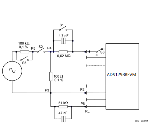
     I use ADS1298REVM, with all JUMPs on default position.

     My question is, what is the best RLD_SENSP and RLD_SENSN configuration on that situation?

     Thank you.

Frank

  • Hi,

    For, "what is the best RLD_SENSP and RLD_SENSN configuration"

    depending on what you mean by "best", and it depends on the applications and usages.

    If you are using an ECG simulator, you can start with all default configurations; doesn't mean it's the best, but good to start.

    Customers need to do trials&errors and data collection&analysis to determine what is best to their cases, applications and usages.

    Thanks

  • Hi ChienChun Yang,

           I ask this question, because when we test our product with the IEC60601-2-47 standard, we failed at the input impedance test.

           And we made the same test with ADS1298REVM, the result is exactly the same with our product.

           In our test:

           1) the ADS1298REVM is powered with a power bank.

           2) We use a laptop which is powered by battery to run the ADS1298REVM software.

           3) We run the test in a room with no electronical equipment.

           With the above 3, there is not a little 50/60Hz noise in our test.

           According to IEC60601-2-47, input a 5mV 10Hz sin wave, when the S1 is open, the Vpp of the signal should not decrease beyond 6%.

           We got 5.0mV when the S1 is close, but  when S1 is open we only got 4.62mV, which is 7.6% decrease.

           The RLD configuration is RLD_SENP3、RLD_SENN3、RLD_SENP2 is enable, which means RLD = (LA+RA+LL)/3.

           And we find that if the RLD configuration changes, the Vpp which changes a little when the S1 is open.

           But, the input impedance should be 500M, isn't it? (current LOFF detection). Why the Vpp drops so much?

           It's very easy to repeat the test use the EVM. And we've searched forum, and find some others ask the same question but have not been solved.

           Best regards,

    Frank

  • Hi,

    Can you explain a little bit in what are the test criteria and procedures for "IEC60601-2-47 standard, we failed at the input impedance test"?

    In the Figure you provide, would you please circle/highlight, which parts belong to the tests setup&circuit and which part is the product?

    I am guessing only the "Recorder" is the product, but just want to confirm.

    Please probe/measure voltage on P4 and P1 without your product to see whether the voltage is expected?

    Also, try use a precise active differential probe to do the same measurement to see&compare the resutls.

    ---------------------------

    what is the 100 ohm purpose their between p3 and p4? what does it try to model or simulate? Can it be changed to much higher resistance?

    Also, is P2 an electrode input to the channel for ECG measurement? Why doesn't it have the similar setup as p1?

    P1 and P2 go to the same channel, correct? Which channel? Do you try other channel?

    -----------------------------------------------

    other thing you could try might be

    1. disconnect all the feedback switch/mux to RLD amp and see how the results go?

    2. power down the RLD amplifier, i.e. not use, and see how the results go? 

    ---------------------------------------------------------------

    FYI, EVM board is not designed for such purposes and tests, customers need to design the peripherals for the products to make the product meet the regulations&standards&tests.

    Thanks

  • Hi ChienChun Yang,

          The above figure is the test circuit in IEC60601-2-47.

          The 100 and 100k resistors are just to make a 0.1% signal, for example get 1mV from a 1V signal generator.

          When the S1 is close, the 4.7nF and 0.62M is bypassed. When the S1 is open, the 4.7nF and 0.62M is connected to the input of the ADS1298R.

          Normally, the input impedance of ADS1298R is >100M. So when the S1 is open, the Vpp of signal get from the ADS1298, should only change a little.

          But, when I take the experiments, the Vpp decrease 12%, which means the input impedance of the ADS1298 circuit is about 0.62/12% = 5.16M, which is far away from 100M. According to the ADS1298R datahsheet, when Current Leadoff method is used, the DC impedance is 500M.


           I have found the cause of the problem. In ADS1298R EVM, there is a respiration circuit including C113/C114/C99/C100/R84/R85/R86/R87/ C108/C109/R96/R97. That makes the input impedance decrease.

          When I remove the C113 and C114, which means the respiration circuit is disconnected, the input impedance is now > 100M.

          So, if we want >10M input impedance, the respiration circuit can not be used.

          I think the respiration circuit will also decrease the CMRR of the whole system.

          My Question is: Is there any way to keep the respiration circuit, while it does not influence the input impedance and the CMRR of the whole system?

          Best regards,

    Frank

  • Hi,

    For  - "I have found the cause of the problem. In ADS1298R EVM, there is a respiration circuit including C113/C114/C99/C100/R84/R85/R86/R87/ C108/C109/R96/R97. That makes the input impedance decrease."

    Yes, as aforementioned, the EVM itself is not designed to meet/pass any regulation/standard tests.

    " When I remove the C113 and C114, which means the respiration circuit is disconnected, the input impedance is now > 100M."

    Yes, thanks for letting me know.

    For, ": Is there any way to keep the respiration circuit, while it does not influence the input impedance and the CMRR of the whole system?"

    Workaround could be, 

    1. use the respiration channel(e.g. Chanel 1) only for respiration purpose not for ECG, so that the test against or with respect to ECG should not apply nor applicable to the respiration channel. In other words. only test the ECG channels.

    2. depending on whether you want to modify the circuit, some thing you could try is to add mux or switch(e.g. JP33), i.e. when it comes to impedance test, direct the switch/mux away/isolate from the respiration circuits.

    3. Do you see there are two OpAmp in buffer(voltage follower) topology, but Not Installed(NI)? may be install/populate those and the peripheral circuits, select OpAmp that typically also have high input impedance.

    ------------------------------------------

    FYI, I hope you know that U11 and U12 and the peripherals are the "Respiration Simulator" circuit, which should not be in a product and should not present or in the way or involve during the tests; they are for evaluation purpose only.

    Appreciate

  • Hi ChienChun Yang,

         Yes, I know that U11 and U12 circuits are for simulator. But that does not made any influence, because I also tried my own board which has no U11 and U12.

         1. Because the ELEC_LA net connect R41 and C113, the respiration circuit will decrease the input impedance of all the channels which connect to ELEC_LA. For the same reason, the respiration circuit will also decrease the input impedance of all the channels which connect to ELEC_RA. That makes the input impedance of channel2 and channel3 decrease. And since WCT=(LA+RA+LL)/3, the other channels also decrease.

             Yes, if we use 2 leads just for respiration purpose named ELEC_RESPA and ELEC_RESPB, which is not connect to ELEC_LA or ELELC_RA, that may work. But 2 more leads are needed, we cannot add 2 more leads on our custom's body, because there is now 10 leads, 12 leads is too much.

         2. But we have to pass IEC60601-2-47 test, to let our product going to the market. The IEC60601-2-47 test requires our product to satisfy the input impedance when the product works. We cannot use a switch/mux to pass the test.

         3. The OpAmp does not work. Because even I remove all the jumps in JP33, the input impedance decrease. The circuits before the OpAmps influence the input impedance.

         4. I have tried changing the R84/R85/R86/R87 to 100M, but it has no influence.

         It seems that, there is no way to satisfy the input impedance requirement (>10M) if we want to keep the respiration function. Maybe we have to remove the respiration function in our product, and if that, we may replace ADS1298R with ADS1298. We don't want to remove the function, but we also need to pass IEC60601-2-47 test.

         Is there any other way? Do you have any information from other customers? I think they also need to pass IEC60601-2-47 test for their medical products.

         Best regards,

    Frank

  • Hi,

    For you point " 4. I have tried changing the R84/R85/R86/R87 to 100M, but it has no influence."

    Could you try

    a. remove all R84/R85/R86/R87?  I think they are for biasing.

    b. Change some or all of them to much higher resistance?

    c. in combination a or b, AND try adjust values for C113, C114, C99, C100 so that the cutoff frequency can pass the test signal?

    What are the test signal frequency?

    ----------------------------------------------

    would you please clarify whether

    it's the CH1 that has lower input impedance?

    or 

    it's the CH1's peripheral(respiration) circuit that leads to low input impedance?

    -------------------------------------------------------

    And, i will escalate this to higher engineer to discuss and get back to you within 24 hours.

    -----------------------------------------------

    Just a reminder&disclaimer, EVM itself is not designed to meet&pass regulations&standards&tests, and customers need to design the peripherals for the products to make the product meet the regulations&standards&tests.

    Thanks,

  • Hi,

    Just for your information(FYI).

    ADS1298R datasheet page 47 clearly states -

    "When this respiration option is enabled, ADS129xR channel 1 cannot be used to acquire ECG signals. If the RA and LA leads are intended to measure respiration and ECG signals, wire the two leads into channel 1 for respiration and channel 2 for ECG signals"

    and page 89 -

    "

    When respiration mode is enabled, channel 1 cannot be used to acquire ECG signals because the internal demodulation circuitry is unique to that channel. ECG signals can still be acquired with the same electrodes used for respiration measurement if they are also connected to another channel. Note the configuration shown in Figure 97.

    "

    Thanks

  • Hi ChienChun Yang,

         Yes, I know that in page 47 and page 89. There is no misunderstanding.

         Channel 1 is not used for ECG in my board or in the ADS1298REVM board, it's only used for respiration.

         For the ADS1298REVM board, Channel 1 is used for respiration, Channel 2 (LA-RA) and Channel 3 (LL-RA) are used for ECG. And since there is respiration circuits including C113 and C114, the input impedance of Channel2 and Channel3 decrease, which cannot meet the IEC60601-2-47 requirement.

         The respiration circuits decrease the the input impedance of Channel2 and Channel3.

         My question is, for ADS1298REVM, is there any way to keep Channel 2 (LA-RA) and Channel 3 (LL-RA) high input impedance (>10M), while Channel 1 is still used for respiration?

         You can test for ADS1298REVM, the input impedance of Channel2 and Channel3 is <10M, which cannot meet the IEC60601-2-47 requirement. And the other channels 4/5/6/7/8 is also below 10M.

        If C113 and C114 is removed, the input impedance of Channel2/3/4/5/6/7/8 is >100M. But since part of the respiration circuit is removed, the Channel1 cannot get respiration signal.

         Best regards,

    Frank

  • Hi,


    Have you tried the methods suggested earlier?

    ----------------------------------------------

    If CH1 is only used for respiration, then why does the ECG signal in channel 1 matter?

    How are the ECG signals in Channel 2 and/or Channel3?

    In other words, the input impedance test should only go with respect to other non-respiration related channels.

    -----------------------------------------------------------------------

    Could you clarify that do your Channel 2 or Channel 3 have any path or connection associated to Channel 1?

    If that is the case, you may try completely isolate Ch2 and Ch3 from Ch1; thus, to make Ch1 completely only for respiration, which is suggested in data sheet i.e.

    while using only Ch1 for respiration purpose and use other channels for ECG.

    ----------------------------------------------------

    May I ask how do you or how was you input impedance test setup?

    Does the standard require to have 100M ohm input impedance?  What is the minimum required input impedance? 

    ----------------------------------

    In addition, may consider the following too -

    What are the input impedance of the 2 OpAmps populated  in your board?

    ---------------------------------------------------------------

    Also, may I ask are you testing the standard using your product PCBA or the ADS1298R EVM?

    Just a reminder&disclaimer, EVM itself is not designed to meet&pass regulations&standards&tests, and customers need to design the peripherals for the products to make the product meet the regulations&standards&tests.

    Thanks

  • Hi ChienChun Yang,

         1. There is no ECG in Channel1, Channel1 is used for respiration. Channel2 is used for ECG (LA-RA).

             But the ELEC_LA net connect the C113/C99/R84/R85 .. to the LA, which decrease the input impedance of Channel2 (<10M).

             In the ADS1298EVM(no R), there is no C113/C99/R84/R85 .., the input impedance of Channel2 is >100M.

             If the C113/C114 is removed from ADS1298REVM, the input impedance of Channel2 will be >100M.

        2. What I test is the ADS1298REVM board, you can easily repeat the test. What we discuss is not my board.

            My question is can we get >100M input impedance, while the Respiration Function is still used.

        3. The  IEC60601-2-47 requires the input impedance >10M. But the ADS1298REVM now is only about 8M.

            But according to the datasheet, the DC input impedance should be 500M when using current LeadOff detection.

        4. We don't need to discuss my board. The ADS1298REVM board is <10M.

        5. "Just a reminder&disclaimer, EVM itself is not designed to meet&pass regulations&standards&tests, and customers need to design the peripherals for the products to make the product meet the regulations&standards&tests."

            Yes. But the input impedance >10M is a very low requirement. It's a very low requirement for any ECG circuit, to guarantee the signal amplitude get from .the patients.

            And if even the ADS1298REVM with respiration circuit cannot meet >10M. No customers can acheive that requirement. And every ECG medical product need to pass the IEC60601-2-47 test.

        6. https://e2e.ti.com/support/data-converters-group/data-converters/f/data-converters-forum/693255/ads1298r-input-impedance-certification-test-issue?tisearch=e2e-sitesearch&keymatch=ADS1298%2010Hz#

            Others also find the problem. But they didn't realize that the input impedance <10M is caused by the respiration circuit.

         In General, the problem is clear: 【All the following test is made on ADS1298REVM】

         1. For ADS1298REVM, the input impedance of Channel2 is <10M.

         2. If C113/C114 is removed, the input impedance of Channel2 is >200M. But the respiration signal can not be get since C113/C114 is removed.

         3. For ECG medical product, the input impedance should >10M.

         4. We need to keep the respiration function, while input impedance >10M. Is there any way?

         5. If 4 cannot be achieved, we have to give up Respiration Function in our product. We may replace ADS1298R with ADS1298.

         You can easily test the input impedance of the ADS1298REVM, which a signal generator and a resistor, as shown in the figure below. You will find the input impedance of ADS1298REVM is <10M. You can also repeat the test with ADS1298EVM, you will find the input impedance >200M (we also have made that test).

         Best regards,

    Frank

  • ADS1298REVM with respiration circuit is not designed to meet and pass any regulation test and/or standards.

    So, it's never suggested to use the exact circuits or use the ADS1298REVM to do any regulation or standard tests.

    Customer will need to design the peripheral circuits and the product to meet and pass any regulation test and/or standards.

    --------------------------------------------------------------

    Have you tried the methods suggested earlier?

    Do you try populate the 2 OpAmps in your board?

    ------------------------------------------

    ADS1298REVM with respiration circuit is not designed to meet and pass any regulation test and/or standards.

    So, it's never suggested to use the exact circuits or use the ADS1298REVM to do any regulation or standard tests.

    Customer will need to design the peripheral circuits and the product to meet and pass any regulation test and/or standards.

    Thanks