This thread has been locked.

If you have a related question, please click the "Ask a related question" button in the top right corner. The newly created question will be automatically linked to this question.

ADS1258: Should ADCINP and ADCINN be connected to 0V, if I am using the internal connection to the multiplexer output?

Part Number: ADS1258
Other Parts Discussed in Thread: OPA320, OPA365,

Hi,

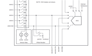
In my application I am not using the facility of adding extra signal conditioning between MUXOUT and ADCIN.  I would like to know:

1) Should I connect ADCINN and ADCINP to AGND (roughly the midpoint of AVDD and AVSS) ?

2) Could I use them as an extra input to the ADC?  Giving me sixteen single-ended inputs and one differential?  Fig. 35 of the datasheet would seem to suggest that this is possible.

Thanks, Mark

  • Hi Mark McLean,

    This post offers an answer to your questions: https://e2e.ti.com/support/data-converters-group/data-converters/f/data-converters-forum/765568/ads1158-ads1158-adcinp-adcinn-pin-can-floating

    Regarding connecting a signal directly to ADCINP / ADCINN: that e2e post says "Also, do keep in mind that the ADC inputs are switched-capacitor type and don't have the highest input impedance. Therefore, unless the input signal source is low-impedance (buffered) then we recommend buffering the input signal with an external amplifier, such as the OPA365 or OPA320." I have honestly not seen this done before, so I can't guarantee that it will work. But in theory it should

    The only drawback to this approach is that it is unlikely there are ESD diodes on the ADCINx pins, since these are not intended to be connected to the outside world. Instead, the ESD diodes are on the multiplexer inputs (AIN0-AIN15 + AINCOM), so that could cause issues. TI's official recommendation would be to use the ADS1258 as intended and only use the ADCINx pins in conjunction with the MUXOUTx pins

    -Bryan