This thread has been locked.

If you have a related question, please click the "Ask a related question" button in the top right corner. The newly created question will be automatically linked to this question.

ADS1015-Q1: circuit design

Part Number: ADS1015-Q1

Hi Expert, 

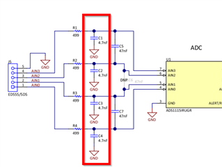
May I know what is the role for C1/C2/C3/C3 here? 

the capacitance with 4.7nF in AIN pin, Can we use 1nF or 10nF instead?

Thanks!

Ethan Wen

  • Hi Ethan,

    The ADS1115EVM has a number of caps that may or may not be required but are shown as an example of various possible configurations.  Capacitors C1 through C4 are common-mode filter caps when used in conjunction with the differential filter caps when measuring a differential input such as AIN0=AINP/AIN1=AINN or AIN2=AINP/AIN3=AINN.  When using this type of measurement the differential capacitors (C5 and C7) should be at least 10 times greater in value than the common-mode filter caps.  This method allows for good common-mode filtering and also allows for good differential filtering while preventing a common-mode filter mismatch of an unwanted differential voltage.

    When AIN0 through AIN3 are used as single-ended inputs (AINx=AINP/GND=AINN) the differential caps are no longer used and C1 through C5 are used to create a simple low-pass RC filter to limit noise and aliasing effects.  You can use any value for the capacitors that make sense for your desired cutoff frequency.  See section 8.1.5 on Analog Input Filtering in the latest ADS1015-Q1 datasheet.

    Best regards,

    Bob B