This thread has been locked.

If you have a related question, please click the "Ask a related question" button in the top right corner. The newly created question will be automatically linked to this question.

ADC3221EVM: Input signal heavily distorted

Part Number: ADC3221EVM

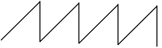
Signal generator outputs an up-ramp signal (100 kHz, 600 mVpp, like following graph), and feed to ADC3221EVM.

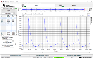
Said up-ramp signal feed to CH1, ADC captured following waveform: 

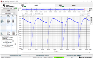
The same up-ramp signal feed to CH2, ADC captured following waveform: 

Therefore, I wonder:

  1. Why the signal captured by ADC is so heavily distorted? Is this normal?
  2. Feeding the same signal, why CH1 and CH2 captured different waveform? CH1's waveform looks flipped, is this expected?
  3. Compared to CH1, CH2's waveform has a very high frequency low amplitude component, its frequency is 12.5 MHz, exactly half the sampling frequency. What could be the cause? 

Please advise, Thank you. 

  • Yuan,

    What is your clock rate? If you are using 25MHZ, in the GUI, in the ADC Output Data Rate section, you must enter 25M, not 25m.

    The signal is distorted due to the input transformers on the EVM. If you input a sinwave you will notice the distortion will be removed. If your application requires a sawtooth input, you will need to use an amplifier.

    CH1 and CH2 are inverted due to the default SMA connectors that are populated on the EVM. If you look at the attached schematic, you will see that the CH2 input SMA uses the inverted path to the input transformer with respect to CH1.

    Regards,

    Jim

    5102.ADC32XXEVM-SCH_C.pdf