This thread has been locked.

If you have a related question, please click the "Ask a related question" button in the top right corner. The newly created question will be automatically linked to this question.

ADS131M03: CRC difficulties

Part Number: ADS131M03

Hi, 

I'm trying to use the CRC DIN functionality of the device, that is, setting the MODE > RX_CRC_EN bit and checking the STATUS > CRC_ERR bit on each NULL command's response. I've been using a Saleae logic analyzer to double check all the data I'm sending, especially with the CRC stuff being in play. I currently also have the MODE > CRC_TYPE bit cleared, meaning I'm using what the datasheet refers to as "CCITT" (though some call it "CCITT-FALSE"). 

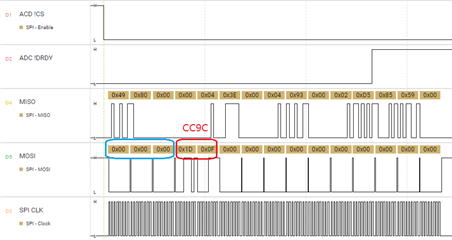
Using this algorithm, when I send a NULL command, I send the following frame (24b word length): 0x 000000 1D0F00 000000 000000 000000, which has the CRC MSB-aligned immediately after the command (as specified in the datasheet). I believe that '0x1D0F' is the correct CRC-CCITT (seed 0xFFFF), but the response to this in the following frame always seems to have the SPI_CRC_ERR bit set. This is especially confusing to me as prior WREG commands respond correctly with the form 0b 010a aaaa ammm mmmm, rather than with the STATUS register that it would if the CRC was incorrect. So I'm pretty confident that my CRC algorithm (which is using a known-working library, the FastCRC library built-in to the Teensy system) is working correctly, and that the device's input CRC check is working. I've also run the test value (['1','2','3','4','5','6','7','8','9']) through the CRC engine and gotten the correct answer (0x29B1). I was thinking that maybe the device's internal CRC engine wasn't re-seeding itself after each check, but since many writes in a row are successful, I don't think that's the case.

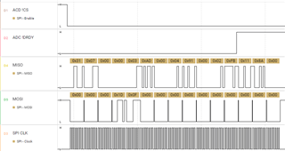
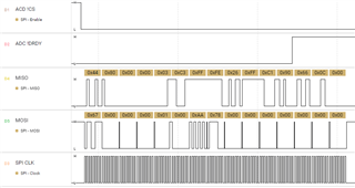
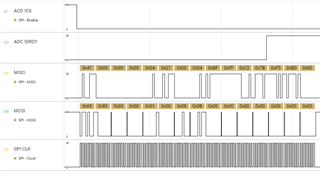
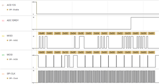
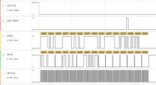
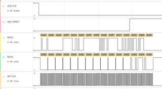
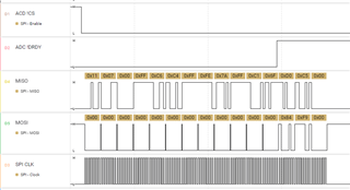
I've attached a sequence of four frames - a WREG, a WREG, a NULL, and a NULL - that demonstrate that the device responds as expected to the WREGs (with the correct CRC), but in the final frame, the response to the prior NULL is 0x3107, which says that the CRC_ERR bit is set, meaning the prior command (0x000 with a CRC of 0x1D04) is wrong.

Can you provide any insight into what might be going wrong here, or some tests I can try to diagnose?

Thanks.

Ben

  • Hi Ben,

    Welcome to our E2E forum.

    It seems that your first timing (the first word is 0x3107) is the last frame regarding your description, and your last timing ((the first word is 0x4980) is actually the third frame. If my understanding is correct, can you please send 0x 000000 000000 000000 000000 84F900 instead of your 0x 000000 1D0F00 000000 000000 000000 on MOSI in your last timing and then check the first word (STATUS) on MISO in your first timing?

    PS: When you send 0x 6700 WREG command, your are write 0x00 to the 0x0E (CH1_CFG) register, you are sending more register data than you need for one register. Also, when you send 0x 6980 WREG command, your are write 0x00 to the 0x13 (CH2_CFG) register, you are sending more register data than you need for one register. Please check.

    Regards,

    Dale

  • Hi Dale,

    Oh my goodness, I apologize, yes, the figures are out of order - from the top, they are 4, 1, 2, 3, as you deduced. 

    I sent the frame as you suggested (middle image, below), but it still responded with the CRC error bit set (bottom image, below). The top image is the first frame after starting the device, a WREG to the MODE register to set the RX_CRC_EN bit (0x3110). I'm pretty unclear why that would have done anything though; 0x84F9 is the CRC for 24 zeroes in a row, which would suggest that (since I have 24b words) the CRC would be programmed with nibbles rather than bytes?

    I'm confused about your PS - the device is configured for 24b words, so (as I understand it) the WREG command is actually 0x670000, which means I'm writing a single register at address 0x0E (the CH1_CFG), and the data that I'm writing is the second word, which in this case is 0x000100. Since each register is 16b, and the words are MSB-aligned (with "the least significant bits (LSBs) are zero-padded to accommodate 24- or 32-bit word sizes." [datasheet, p. 36]), I believe I'm writing 0x0001 to CH1_CFG register, which is setting the input multiplexer for CH1 to be "shorted". The final word in the frame (prior to two frames of zeroes, as required ("On DIN, the host provides the command, the command CRC if input CRC is enabled or a word of zeros if input CRC is disabled, and three additional words of zeros." [datasheet, p. 35])) is the CRC of the prior two words, i.e. the WREG and its data (0x 670000 000100). Do I have something wrong with this?

    Thank you.

    Ben

  • Hi Ben,

    I will look into the details and get back to you soon, thanks.

    Regards,

    Dale

  • Hi Ben,

    I'm sorry for the late response and also I apologized for the confusion to you. What I tried to say was "01" written to the registers, not "00", this was my typo error. I also noticed that 0xAA78 and 0x080B were your CRC words. Please ignore my PS above.

    I reproduced your exact commands and timings on my M04 hardware by using a specific software today and also I tried different frame formats, however I saw a 0x110F was shown as the first status word which indicated that an input CRC error occurred. I will talk to the design engineer and try to get it back to you by tomorrow. Thank you for your patience.

    Regards,

    Dale

  • Hi Dale, 

    Thank you for clarifying and checking in. I'll look forward to hearing what the design engineers say. 

    Ben

  • Hello Ben

    The design engineer is on vacation this week. Also, his manager is on business travel until 5/19, I'm not sure how fast I get his response, so please allow a delay of few days to get back to you. Thank you for your understanding.

    Regards,

    Dale

  • Hi Ben,

    Thank you for your patience. Please use 0xCC9C instead of 0x1D0F as input CRC according to the format in the following timing. Your 0x1D0F is the CRC for 0x0000 which is incorrect, 0xCC9C is the right CRC for 0x000000. Please notice that NULL command is a 16-bit command but the word size is 24-bit, so the input CRC should count 24 zeros not 16 zeros.

    Best regards,

    Dale

  • Face palm I feel silly. Thank you! Worked immediately.