Other Parts Discussed in Thread: PGA113
Hello,
I plan to use discrete components to make a simple amplifier with variable gain, as show below: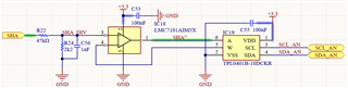
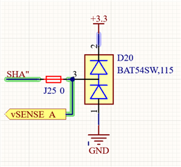
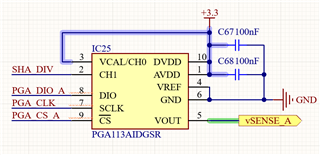
The signal "vSENSE_A" goes to the ADC to be read.
My intention is to capture a PWM signal (max frequency of 200kHz) with max amplitude of 60V and min amplitude of 6V.
So for the worst case, the 60V would be reduced through the resistor divider at the input of this circuit, and then the circuit amplifies it by a factor related to the position of the wiper from the dig pot.
There are some questions below:
1. After selecting a value for the wiper position through the I2C, will pin 5 and 6 impedance vary or it will remain the same (as a real resistor divider)? My question is to understand whether this "digpot" hold the resistor divider ratio or it floates a bit, and if so, how much does it floates (?), as any source of variation in these pins that could dirt the signal.
2. What would be the error caused by this supposed fluctuations in this purpose? Is it a suitable solution?
3. For the image below, in case of using a PGA113 instead of a discrete circuitry, should I connect the AVDD pin to the same DVDD source? (acceptable error: <5%)