This thread has been locked.

If you have a related question, please click the "Ask a related question" button in the top right corner. The newly created question will be automatically linked to this question.

ADS1298ECGFE-PDK: Dev Kit software freezes while collecting data from ADS1298

Part Number: ADS1298ECGFE-PDK
Other Parts Discussed in Thread: ADS1298

Hi there,

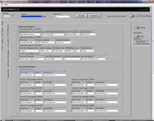
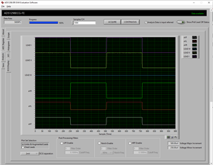
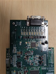
I am using ADS1298ECGFE-PDK with its companion software to receive data from ADS1298 (which is already on ADS1298ECGFE-PDK).

Unfortunately, I have noticed erratic behavior in the companion software while receiving signal data from the AFE.

Software gets stuck to 0% and doesn't complete the process.

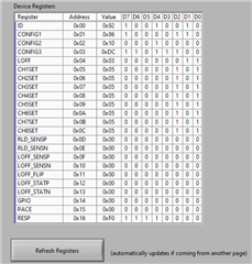
All the register reading is working fine.

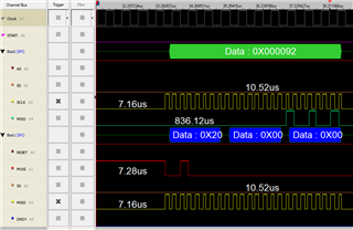
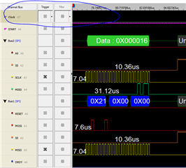
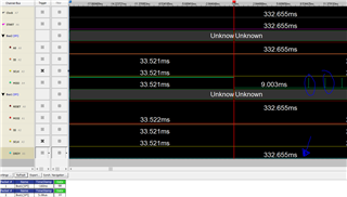
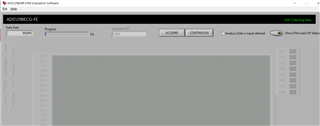
Please see attached images;

This is where it get stuck, after pressing AQUIRE button.


Is this a known issue?

Really appreciate any help in fixing this issue.

Best regards,

Bhargav

  • Hi,

    This is not a known issue.

    In the about Tab, Do you read the Device ID and Firmware version?

    Have you changed any jumper settings on the board?

    Try shut down the GUI and disconnect the board and restart computer and connect board and launch GUI again.

    Then, try use ACQUIRE button.

    Thanks

  • In the about Tab, Do you read the Device ID and Firmware version?
    Yes

    Have you changed any jumper settings on the board?
    No, all power rails reads correctly.

    Try shut down the GUI and disconnect the board and restart computer and connect board and launch GUI again. Then, try use ACQUIRE button.
    Done plenty of time but no joy!

    As mentioned earlier I'm able to Read and change register values accurately however it freezes only when I try to capture the data either way Acquire or Continuous tab.

    1. What's the purpose of EEPROM on the AFE board? 
    2. What's the default register values should I have?

    Best regards

  • Hi,

    EEPROM is to store the sampled/acquired signal data before streaming to MCU and PC.

    On the

    See if you could configure like below and try ACQUIRE again -


    You may try the Reset Options on the right as well.

    E.g. select the Device Defaults and then click Reset

    and then, select Programmed Defaults and then click Reset.

    Thanks

  • Thanks
    I'm using same Register setting as shown in the image, tried with both NORMAL electrodes and TEST but still no luck.

    Tried RESET with device default but still the issue persist.

  • Hi,

    Would you mind installing the GUI on a different computer?

    Thanks

  • Sure, will do that and update you by tomorrow.

    In the mean-time I have noticed START pulse generated by EVM board is approx. 20ms long, by manually making it longer (approx. 200ms) the EVM is able to complete the acquisition of data!


    Could you please explain this behavior, what's the min/max duration of START pulse needed for successful acquisition of the data?

    Best regards,
    Bhargav

  • Hi,

    Do you mean now you are able to use the EVM and GUI to acquire the data?

    According to datasheet page 51,

    9.4.1.1 Start Mode

    Pull the START pin high for at least 2 tCLK periods, or send the START command to begin conversions.

    and

    9.4.1.1.1 Settling Time

    The settling time (tSETTLE) is the time it takes for the converter to output fully-settled data when the START signal is pulled high..

    Table 12. Settling Times for Different Data Rates (tSETTLE)

    Thanks

  • Thanks,

    9.4.1.1 states START pin to be high for at least 18.44ms, so 20ms make sense.
    However, I'll debug further with DRDY signal along with START.

    Do you mean now you are able to use the EVM and GUI to acquire the data?
    by manually providing START pulse which is not ideal. So I don't consider it to be resolved yet.

    Best regards,
    Bhargav

  • Hi,

    I am confused.

    Do you use the EVM and GUI as they originally came?

    If yes, they should work right out of the box, i.e. don't need to manually change/alter the START pulse.

    Thanks

  • Do you use the EVM and GUI as they originally came?
    Yes.

    If yes, they should work right out of the box, i.e. don't need to manually change/alter the START pulse.
    it used to be but not anymore Disappointed. Erratic behavior!
    Which concern me about reliability of the product/EVM too, unless TI has a reasonable explanation.Disappointed

    I have tried Program Default reset and Device default resetting too but no luck.
    Not sure that EEPROM has any role to play in this?

    I do not have logic analyzer with larger buffer to see captured samples, however I'll try to do some debugging in due course.
    In the meantime if you have access to Logic analyzer/ already captured trace with START, DIN, DOUT, SCLK and DRDY signal (not the screenshot from Datasheet Wink ) then please share.
    Ideally with 500sps and Channel Input with Test waveforms.

    Best regards,
    Bhargav

  • We haven't encountered that person needs to manually alter any signal if wants to use EVM and GUI as default usage.

    It's suggested to try the EVM and GUI with a different computer if you are sure everything was in default settings.

    ----------------------------------------------------

    If your are looking for SPI signals, you may use this as a reference.

    https://e2e.ti.com/support/data-converters-group/data-converters/f/data-converters-forum/775262/faq-ads129x-i-m-having-trouble-communicating-with-my-ads129x-device-via-spi-what-debug-steps-i-should-try/2868427#2868427

    ---------------

    Thanks

  • Hi ChienChun,

    After bit of debugging I've found when the MMB0 board sends 0x08 command to START the acquisition the EVM software completes the acquisition process.
    Now I'm not seeing any 20ms pulse on START pin, which is weird!

    Could you please confirm, 
    Does MMB0 board always use 0x08 command to START the acquisition or it can be programmed to start the acquisition with HW START pin?
    How to configure MMB0 board to use 0x08 command only?

    Best regards,

    Bhargav

  • Hi,

    Your statement looks a bit conflicting and confusing to me. Would you please clarify?

    and

    Could you probe and provide screenshot/picture of 

    triggered by START pin signal during and right after power up of the EVM?

    and 

    show me where you see the START command of 0x08h on the scope?

    Thanks

  • Hi ChienChun,

    Your statement looks a bit conflicting and confusing to me. Would you please clarify?
    Please explain which part you are struggling to understand?

    MMB0 board was pulling START pin HIGH when I have experienced erratic behavior where EVM software freezes while acquiring data from the AFE.
    However, when I tried acquiring data from the AFE yesterday (using the same set-up), the MMB0 board sending START command to initiate data acquisition and EVM software was able to complete the process without getting hang.

    So the question are;

    1. Does MMB0 board always use START command to initiate the data acquisition?
    2. Is there any situation where  MMB0 board will pull  START pin HIGH to initiate the data acquisition?
    3. If answer of q.1 and 2 is Yes then how to program/configure MMB0 board to use START command only and not to pull the START pin HIGH?

    I have also read in datasheet which suggest STANDBY mode will make ADS1298 to respond REGISTER read/write commands but not data acqusition.
    Is my understanding correct?

  • Hi,

    Thanks for clarifying. I will get back to you around 6/20.

  • Hi,

    Just to clarify between the "Conversion" and "Acquire/Acquisition"

    START pin or START command is only for to START the ADC conversion, not yet for reading the sampled signal from the ADS i.e. not yet acquire the sampled data from ADS to GUI.
    "When the START pin is pulled high, or when the START command is sent, the device ADCs convert the input signals", but still not yet acquired/read the data from ADS to GUI.

    ---come back to the Acquire and START------------------------

    The way GUI and MMB0 were coded is that when Click the "Acquire", yes, it uses START command to initiate the ADC Conversion and RDATAC command to initiate the Read Data Continuous mode.

    If JP22 is installed, as soon as the EVM and MCU is powered up, a high signal is sent to the START pin. This could have started the ADC conversion(not acquisition).

    Then, when GUI launches, a low signal is sent to pull the start pin to low.

    So, the GUI and MMB0 are already using the START command.  The START pin is low.

    ----------------------------------------------------------

    by the way, no signal pin needs to be manually changed from EVM to acquire the data and no freezing -

    Thanks

  • Hi ChienChun,

    The issue of not been able to acquire sample and EVM software being stuck on 0% still persist.

    I have tried few more things as below;

    1. Removed MMB0 board and tried communicating with external MCU.
    2. I'm able read 0x92 ID and all Registered.
    3. I'm able to Write to all writable registers.
    4. JP18 pin2 shows proper clock signal when external clock is used

    image is attached 

    5. After removing JP23 and setting CONFIG1 to 0x16 (setting selecting CLK_EN = 1) Pin2 of JP18  doesn't show clock signal at all!
    Image is attached;

    Does this mean internal oscillator is not working?

    6. As mentioned in Datasheet the DRDY pin should toggle if Start pion is pulled high(by external MCU), 

    however, I do not see DRDY pin toggling. DRDY pin always stay LOW!

    Could you please explain such behavior of the AFE1298 please. It is taking really long to resolve this issue.

    Best regards,

  • Hi,

    I don't think this should be the correct route and path. EVM and GUI should work right out of the box without this debugging or troubleshooting effort.

    Could you try install the GUI on a different computer first, and then use the EVM on that computer? Make sure you reset everything back to factory default.

    Thanks

  • Hi,

    I tried installing GUI on another PC however the problem still persist.
    When EVM is connected to PC and trying to acquire signals (pressing Aquire button) MMB0 board sends 0x08 , 0x10 commands and (i believe) waits for the DRDY to go LOW which never happens. Instead i'm seeing DOUT pin toggling after 9ms and every 2ms after that. Image is attached.

    Seems like the EVM is defective, if you have no obvious answer to it's operation.
    What do you suggest?


    Best regards,

  • Hi,

    Please check whether the EVM jumpers are setup like the following -

    If the issue still persists, feel free to contact the source of purchase and request a return or replacement.

    Thanks