This thread has been locked.

If you have a related question, please click the "Ask a related question" button in the top right corner. The newly created question will be automatically linked to this question.

TSW14J58EVM: CAPTURE_FLAG_NOT_SET error in HSDC PRO

Part Number: TSW14J58EVM
Other Parts Discussed in Thread: ADC12DJ5200SEEVM, , ADC12DJ5200RF, ADC12DJ5200SE, LMK04828, LMX2594

We are connecting TSW14J58EVM (5.5 V, 4 A Power Supply) with ADC12DJ5200SEEVM (12V, 1 A Power Supply). We modified the ADC12DJ5200SEEVM to use onboard clocks. 

We are following these steps after giving input signal-

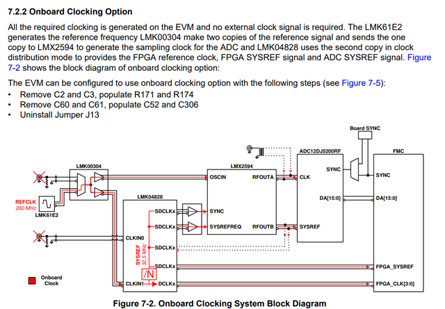
1. In ADC12Dxx00RF GUI we are using onboard clocks as clock source.

2. Fs = 4000 MHz we are choosing with JMODE0 as sampling and calibration mode. Then we click "Program clocks and ADC"

The status of EVM tab is - 

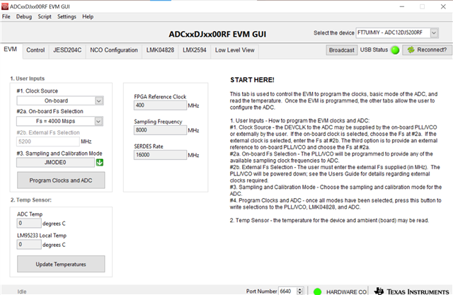
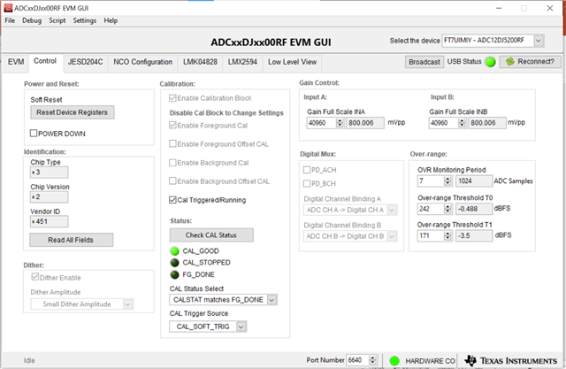
3. In Control tab we click Cal Triggered/Running once, then click it again. [ We tried enabling and disabling background calibration both] 

The status of Control tab is -  [ Cal_stopped, FG_DONE LEDs not glowing]

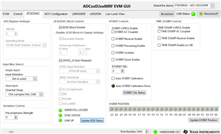
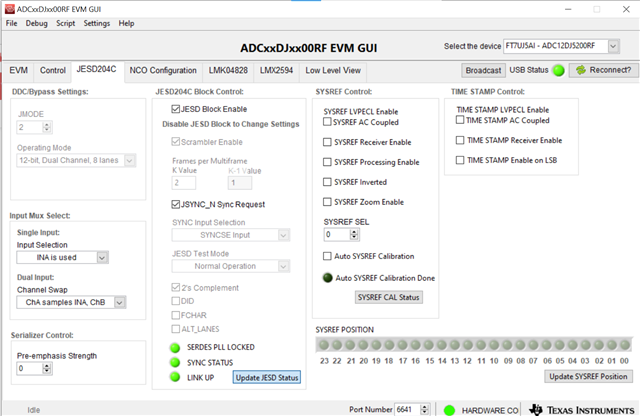
The status of JESD204C tab is - ( SYNC status LED is glowing sometimes but other LEDs are not glowing anytime )

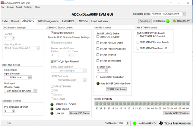
The other tabs are kept unchanged from default options. 

In HSDC pro software we are following these steps-

1. Confirming the serial number of TSW14J58EVM.

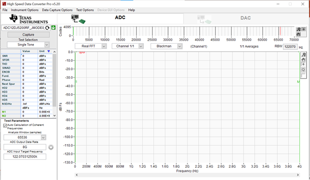
2. Selecting ADC12DJ5200RF_JMODE0 & downloading the firmware. Entering ADC output data rate. 

3. Selecting test, data view, channel view.

4. Now, we are clicking the capture button.

Then the following message pops up- 

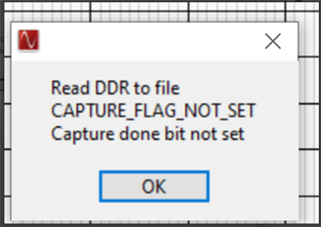
We tried it multiple times but the same error pops up every time. We are stuck with this problem over a week and require urgent help from someone.

  • Hi Anomitra,

    We are looking into this, please give us a few days to respond.

    Have you verified, with an oscope, all the on board clock source configuration as you referenced above is giving the correct sampling rate & FPGA reference frequency for JMODE0?

    Thanks,

    Rob

  • Hi Anomitra,

    Additionally, can you provide a list of modifications which were made to enable the onboard clocking? This in addition to verify clocks are present with an oscilloscope will help rule out hardware being the issue.

    Thanks, Chase 

  • Hi Chase,

    These are the modifications (in bullet points), we made to use on-board clocks.

    Regards,

    Anomitra

  • Hi Rob,

    We tested the ADCEVM clock outputs a week ago & all clocks (under 2.5G DSO) we could verify were working fine. We would recheck that & report to you by tomorrow. 

    Also, can we check the reference clock from TSWEVM somehow to ensure its reaching the FPGA?

    Thanks,

    Anomitra

  • Hi Anomitra,

    Are you able to verify to connections you made when making the modifications. A couple of common problems we see are when inserting C52 and C306 resistors are used, to function correctly they both C52 and C306 must be 0.1uF capacitors. We also see that when changes like this are made and components are reused the heat from soldering can damage the component and make them unusable so we recommend using new components when making the swap. We made these changes and were able to verify it worked correctly, another thing to verify the clock is working properly is to check the 3 LED pins in the JESD204C tab of the gui should all be lit up, like this. This means the device is getting the clock, and if that is lit up and it is still not working then I would try and verify the clock signals with an oscope.

    Thanks,

    Eric

  • Hi Eric,

    We can confirm that, we modified the EVM to use on-board clocks as per your instructions.
    We used different ADC12DJ5200SE EVM and we were able to get the following JESD204C tab status

    Still the same error pops up.

    So, we tested the on-board clocks in oscope.

    This is the outcome-

    LMK61E2- o/p is fine.

    LMK00304- o/p is fine.

    LMK04828 some outputs are working, some are not working. (Heavy check mark sign indicates working, X sign indicates not working).

    Please note, that we changed the LMK04828IC and getting the same results for clock again.

    For LMX2594, sampling clock output is fine but SYSREF signal is not coming out.

    So, I have the following questiions-

    1.I am not sure all these clocks are required for the operation. Can you help us to have some clarity about that?

    2. Do you recommend using reference clock instead of on-board clock? [If you do, what should be the high and low levels of the clock. We have DTG5078 pulse generator can we connect it directly to the SMA REF CLK?]

    3. Do you recommend any other hardware debugging other than changing ICs?

    Thanks,

    Anomitra

  • Anomitra,

    When you say that some of these clock outputs are not working, can you explain what you mean by this?

    Thanks