This thread has been locked.
If you have a related question, please click the "Ask a related question" button in the top right corner. The newly created question will be automatically linked to this question.
Dear Support,
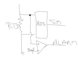
I would like to measure my RTD sensor, and this chip seems more thn capable to do so. One thing i am not sure, but I need is some safety feature, an Alert signal or safety shutdown basically what I would need is an SPI independet signal if my temperature goes whatever Kelvin I set. To rephrase my question, I measure my RTD and if it goes above 200C degree I need to shut the system down, independently from the SPI beacuse its not considered safety reliable way
Thank you
Zsolt
Hi Zsolt,
Unfortunately the ADS124S08 does not have this type of capability. The ADC converts a voltage and not a temperature. The ADC can be used as a ratiometric measurement where if the excitation (such as a current) that is used for both the RTD (a resistance) and the reference (also a resistance) the code value returned will represent the resistance of the RTD in proportion to the reference resistance. Some method of conversion (LUT or polynomials) will be required by the host processor to convert the resistance to a temperature. There is not a direct way to program the ADS124S08 to read or compare the measured value to a specific temperature.
What I have seen for other customers do is to use either a comparator or another ADC that has comparator capability. Which method used would depend on the required functional safety rating. A comparator would be a fairly simple method to trigger at a designed voltage threshold. The comparator input voltage would be across the same RTD sensor connected in parallel to the ADC and when the RTD voltage is greater than the threshold voltage an alert can be triggered.
Best regards,
Bob B
Hi Bob,
Thank you for your reply, that was exactly what I was thinking of. In both cases where would you put the ADC/Comparator?
Like this?
Thank you in advance.
Hi Zsolt,
That is the basic concept. How the RTD and comparator are actually implemented may be slightly different based on actual system design and excitation method for the RTD. See A Basic Guide to RTD Measurements for different types of configurations and RTD implementation.
Best regards,
Bob B
Hi Bob,
Thank you again, really helpful design guide. One last question though, please forgive me my ignorance I am a tiny bit confused about the measurement with low-side reference. Can this be used separately with a delta-sigma ADC to produce Alarm signal? What is the general purpose of the low side ref?
Thank you Bob.
Hi Zsolt,
The low-side reference allows the measurement to be ratiometric. In the case of an RTD, the ratiometric measurement becomes a ratio of the RTD resistance to the the reference resistance. Why this is preferable is because the same excitation to excite the RTD also excites the reference which removes any drift of the excitation source. Also, the reference resistor adds a bias to the RTD input to within the proper input range of the ADC so that the PGA and possibly gain can be applied.
The reference input voltage can be monitored by the ADC and the STATUS byte used to indicate if there is a reference voltage issue (which is usually indicating a wire break issue for the RTD). However the reference voltage itself cannot be used to indicate an over-temperature issue. Only the RTD can indicate the temperature change.
Best regards,
Bob B