This thread has been locked.

If you have a related question, please click the "Ask a related question" button in the top right corner. The newly created question will be automatically linked to this question.

DDC114: ADC value drift

Part Number: DDC114
Other Parts Discussed in Thread: DDC264

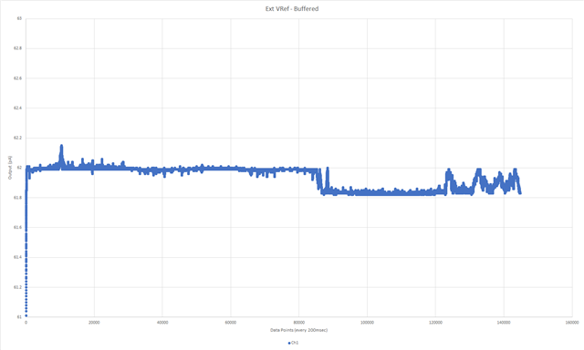
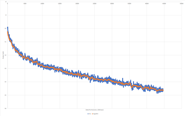
I am currently investigating a problem with DDC114, where the ADC value is gradually changing with time, as shown below. Moreover, the extent of this drift differs among different boards. Is this a known issue associated with DDC114? If so, are there any potential workarounds available to address this issue?

Additionally, I would appreciate your kind recommendation for a pin-compatible replacement IC that offers superior performance compared to DDC114IRTCT.

  • Hello David,

    Your vertical scale is negative... Do you mean that the current is actually flowing out of the DDC? Is your input connected to something while you are doing this test?

    And your horizontal scale is roughly 2hrs? So, is the plot showing that current at the input decreased by about 4pA in 2hrs? 

    What is your integration time? Maybe it is 200ms? 

    Regards,
    Edu

  • Hi Eduardo, 

    Integration time is 2ms and the input range was set to 350pC. The vertical axis shows the measured current (in pA) derived from the following formula:

       current = (((float) adc_output / FULL_SCALE_ADC) * full_scale_picocoulombs * 1000000.0) / integration_time_usec;

    where:

       FULL_SCALE_ADC = 4278190080.0

       full_scale_picocoulombs = 350

       integration_time_usec = 2000

    The horizontal scale is about 2.5 hrs, and yes, the measured current dropped about 4.4pA over this period of time. The input is open, so essentially, it's just measuring noise.

    FYI, the voltage reference is not buffered, but directly connected to the VREF pin of the DDC114 with a 5.6uF cap as shown below. I know this is not recommended, but would this cause the output drift?

    Regards,
    David

  • Sorry but something doesn't match...

    Where you get that FULL_SCALE_ADC = 4278190080.0? The device outputs 20bits, so max output is ~1M. Maybe you are representing that somehow in a different notation (?), but please, use decimal just to simplify the discussion.

    I'll have to check on the effects of not buffering the reference. Certainly it can have effects on the offset but not sure about drifting over time... BTW, is the drift due to time or could it be due to temp? I mean, do all boards drift the same way? (You say they differ but don't give much details)

    Regards,
    Edu

  • My apology, I forgot to mention that we are applying a filter to the raw ADC value, so we multiplied the ADC full scale factor by 4096 to simplify some calculations.

    The ADC values on all boards are experiencing drift, but each board shows a different pattern. Over the same period of time, some may have smaller drift while others have larger drift, but what remains consistent is that all values gradually decrease (or become more negative) as time progresses. However, we've observed that when the power is turned off, the ADC values increase and return to their original values after several hours. I don't believe this behavior is influenced by room temperature, but I do suspect it's related to the ADC getting warmed up during operation. What do you think?

    Additionally, it's worth noting that each board has different offsets, which could be a result of not having a buffer of the reference.

  • Hi David,

    If the drift is about 4.4pA and you got 2ms integration time, we are talking about 8.8fC or 25ppm over 2.5hrs. 

    I would run that numbers against the spec table (although conditions are not exactly the same) but:

    • It doesn't look ibias current or ibias drift because although it could be within spec (10pA), looks quite big for all your boards (spec 0.1pA typ)
    • Doesn't look either like PSRR, which spec is 25ppm per V of change (when you said supply, that is the first thing I thought but no...). 
    • Offset temp drift spec (+/-0.5 ppm/C typ, +/-3 ppm/C max) doesn't seem would account for this much. Have you checked if cooling the part down changes the value this much?
    • I was going to go for offset drift stability, with 1ppm of FSR/minute, worst case. That could account for it, but the RC behavior doesn't seem like it (it would be more like a random walk).

    Maybe something is settling at the reference input... Do all 4 channels move together and the same?

    In that sense, I don't know about drift, but I know from newer devices like DDC264 that no ref. buffer will mean bad results. So, regardless of this topic, ref. buffer it is a must.

    Regards,

    Edu

  • Hi Eduardo,

    It appears that the drift observed in the ADC was a result of not using a buffered Vref. I built a test circuit using a separate Vref and Opamp to replace the original onboard unbuffered Vref and repeated the test.

    As you can see below, although the offsets are much higher due to long jumper wires, the ADC output with external unbuffered Vref shows the same drift pattern as the result with the onboard Vref, which was also unbuffered. In contrast, the ADC output with buffered Vref shows minimal drift over the course of ~8hrs. 

    I'm interested in understanding the mechanism behind how the unbuffered Vref could cause such drift within the ADC. Do you have any insights or ideas that could explain this phenomenon?

    Results with non-buffered voltage reference:

    Results with buffered voltage reference:

    Regards,
    David

  • Alright! Mystery solved... Thanks for the update.

    I sent this question to one of our designers yesterday. He wasn't involved on the design of this device, but anyhow, he may have some thoughts. I'll let you know when I hear back.

    I'll mark the problem as resolved but not sure what happens if you approve it. May close the thread, so, please wait couple of days...

    Regards,
    Eduardo

  • Hello David,

    Got some speculation from two designers (none the original designer of the device)... but the bottom line is that there is no easy explanation. We don't know. The reference should not influence the offset codes as everything is ratiometric when there is no external signal. It is also strange that the change is so slow. Hard to attribute to an electrical time constant. We could go much deeper, requiring experiments on your side and analysis on our side (opening up the DB, etc) which makes no sense as the problem is solved following what is recommended on the DS... 

    Best regards,
    Edu