This thread has been locked.

If you have a related question, please click the "Ask a related question" button in the top right corner. The newly created question will be automatically linked to this question.

ADS7861: INCORRECT SERIAL OUTPUT DATA

Part Number: ADS7861

We are debugging our circuit that include an ADS7861 as main AD Converter.

The ADC is driven by a clock of 833KHz. We use MODE IV to acquire data by using a TMS5704357 micro controller.

The inputs are configured as single ended with the negative input connected to the REFOUT pin (2.5V).

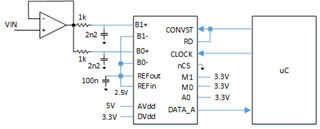
The positive input (VIN) span from 1.4V to 4.8V and is connected to B1+ and B0+ inputs with an OPAMP buffer.

By acquiring the serial data we note that the output code is completely wrong. With an input voltage (VIN) equal to approx 2V we acquire a digital data from serial output DATA_A equal to all ZERO (zero in decimal) for both B channels, see next picture.

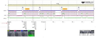
We expect that whit an input voltage of 2V the output converter data would be negative since 2V - 2.5V = -0.5V

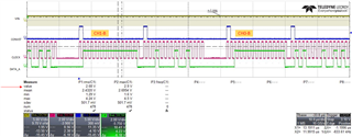
With an input voltage (VIN) greater than 2.5V digital data from serial output DATA_A equal to all ONEs (-1 in decimal) for both B channels, see next picture.

We are unable to find where the problem is.

Thanks for your help

  • Hi Nicola,

    I don't see anything wrong necessarily with your schematic, and you are correct in that the 2V in should give -0.5 to the Bx+ channel inputs.  When you see the 0xfff output, how far are you going above 2.5V in?  The ADS7861 has a binary two's compliment output, from 2.5V in through 5V in the output should go from 0xFFF to 0x000 and up to 0x7FF.  Can you verify with a o'scope probe that the voltages at the REFout/in pins is a stable 2.5V and then verify that voltage is present on the (-) inputs? 

  • Hi Tom,

    thanks for the reply.

    Yes, both reference and input voltage (VIN) has been correctly verified.

    I have a doubt for what concern the digital supply (Vd). The datasheet doesn't have a dedicated specification for the digital power supply, but only for the analog power supply. In fact the device is defined as a single supply device, "The ADS7861 is a high-speed, low power, dual, 12-bit A/D converter that operates from a single +5V supply" (Introduction, page 8)

    In the PIN description table both supply voltage are defined as 5V.

    Again at page 9 it says that:

    "Care must be taken regarding the absolute analog input
    voltage. The +IN input should always remain within the
    range of GND – 300mV to VDD + 0.3V"

    So in my case if 3.3V is allowed for digital power supply, the analog input (VIN) is out of range (my VIN span from 1.4V to 4.8V)

    I need to figure out how to change my digital power supply.

  • Hi Nicola,

    Are you getting the expected results from CHAx?

  • CHA is not currently driven.

  • OK, if you can add those channels or let us know if having 5V on DVdd makes a difference, we would appreciate it.