This thread has been locked.

If you have a related question, please click the "Ask a related question" button in the top right corner. The newly created question will be automatically linked to this question.

AMC7812: There is a 400-500mV voltage in the ADC single-end input port when the sampling voltage is zero.

Part Number: AMC7812
Other Parts Discussed in Thread: INA168,

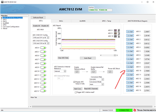
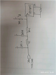
Hi, there is a problem when I use INA168 and AMC7812. There is a 400-500mV voltage in the ADC single-end input port (CH0) when the sampling voltage is zero. In this situation, there is only a 1k-series resistor and no buffer between INA168 and AMC7812. In addition, the output load RL of INA168 is 100kΩ. when the output voltage of INA168 is zero, the input of AMC7812 is up to 400-500mV. however, when I added a buffer before the ADC input, this phenomenon disappeared. So i want to know what caused that strange phenomenon (400-500mV at the input port with 0V-sample voltage)

  • Hi Steve,

    When you measure the voltage on the ADC, do you see 0V or 400-500mV? From what I understand, it should be 0V, correct?

    Thanks,
    Erin

  • Hi Guthrie, sorry for the wrong description. I reconfirmed the test results.

    1. when the ADC single-end input port (CH0) of AMC7812 is floating, there is an approximate 2.4V voltage in the floating ADC input Pin. And the lower the sampling rate, the lower the voltage at the floating ADC input Pin. The same phenomenon is observed on the floating pins of the other ADC channels.

    2. When the ADC single-end input port is connected to the INA168 (with RL=100kΩ), and the sampling current is ZERO, the ADC input port is 400-500mV.

    I'm speculating that there's some ADC structure inside the AMC7812 that makes the voltage appear at the input pins when the ADC pins are floating. and due to the output impedance of the INA168 circuit, the floating voltage is pulled down to 400-500mV. In addition, when a buffer is added before the ADC input, due the lower output impedance of the buffer, the floating voltage is pulled down to 0mV and as a result, the current signal can be accurately acquired and converted unaffected by the floating voltage.

    I wonder if my understanding is right?

  • Hi,

    For your second question, INA168 with RL = 100K, you need to buffer the INA168 output before connecting to ADC inputs.

    We have a SAR ADC implemented in AMC7812 which have an input leakage current max of 10uA. If you connect a 100K load resistor to this analog input pin, you can have a dc voltage (max) of 10uA * 100 k = 1000mV.

    Please share your schematics to comment on the first question

    Regards,

    AK

  • Hello, I have used the AMC7812EVM to take a test. When the ADC channel is float, there will be voltages at the ADC pins, as shown in below picture.

    Especially, when the ADC input is not an ideal voltage source (e.g. ina168), it is easy to introduce errors. 

    The schematic is shown as below.

  • Hi Steve,

    For the first part of your question, voltage appearing on floating ADC pins: There is an internal sampling capacitor in the SAR ADC. When the pin is left floating, it will charge to some arbitrary value in reference to VREF. That is why you see some voltage when the ADC input is floating.

    Adding a buffer (or a large resistor to ground) should help remove this phenomenon by giving the internal capacitor a voltage to charge to.

    Let me know if you have any other questions.

    Thanks,
    Erin