- Ask a related questionWhat is a related question?A related question is a question created from another question. When the related question is created, it will be automatically linked to the original question.
This thread has been locked.
If you have a related question, please click the "Ask a related question" button in the top right corner. The newly created question will be automatically linked to this question.
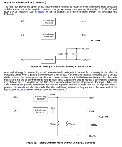
Hi! I am working with biosignals (EMG and EEG) and I have some questions about the use of ads129X IC in a PCB project. I am familiar with ads1293 but my questions may apply to the ads1298. I am trying to understand the differences in two methods reported in datasheets of ADS devices. Here is a print about what I am talking about. (The print is from ads1298 datasheet)

Seems to me that the second strategy is applied to remove de DC offset but presents poorer performance regarding reducing the noise of the signals. Can someone explains to me when I should use each of the approaches? And what about using the two approaches at the same time? Is it redundant and they might compete for driving the common-mode?
And another topic is patient safety. Any of those approaches is better regarding safety? Are there any TI's Application Note regarding safety for patients?
Best.
Hi,
The figure you put on the top i.e. using a dedicated RLD electrode is always suggested and recommended as using RLD electrode significantly help improve&achieve better SNR, CMRR, signal, performance, etc.
The figure at the bottom is less recommended as the advantages of using RLD electrode mentioned above degraded&diminished. Only use the bottom approach when RLD electrode is really not available.
Above two statements are well known and have been proved in ECG field, so to answer the questions
" And what about using the two approaches at the same time? Is it redundant and they might compete for driving the common-mode? "
Using RLD electrode is still recommended; it's optional for customers if they want to do tests&V&V by themselves to understand the idea.
One can also take a look of this application note about RLD and CMRR -
Thanks