This thread has been locked.

If you have a related question, please click the "Ask a related question" button in the top right corner. The newly created question will be automatically linked to this question.

TLA2024: Datasheet suggested footprint bug

Part Number: TLA2024

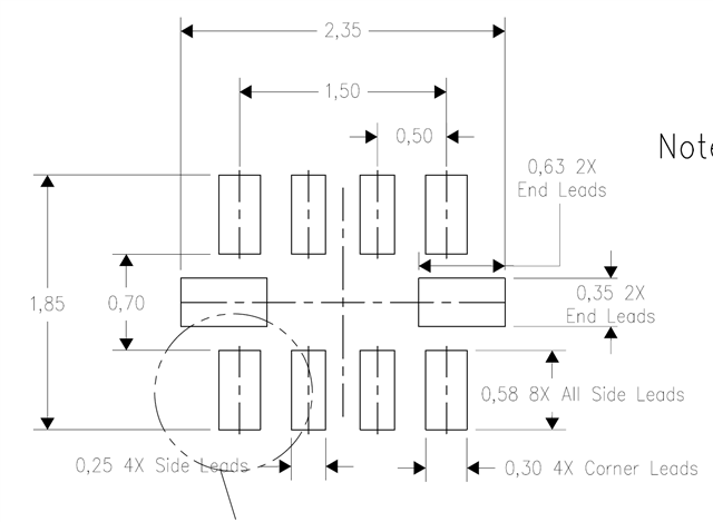
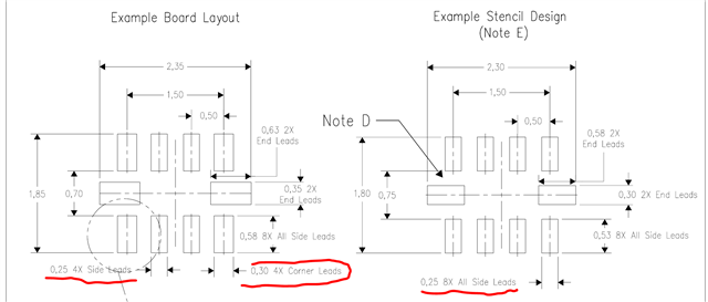
Example Board Layout wrong measurements wrong:

In the TLA2024 Datasheet page 34 the total measurement of the suggested Footprint is 1.85mm.

But the sum of 0.58mm + 0.58mm (for both pads) and the distance between the two pads 0.7mm is not 1.85mm it's 1.86mm!

  • same for the stencil btw.

    1.8mm is not 0.75+0.53+0.53..


  • for consistency reasons I would also expect the solder paste for the 4 middle pads to be smaller than for the 4 outer pads:


    I would suggest to change this to 0.2mm solder paste for the 4 middle pads, then it looks like this (0.025mm solder paste reduction on all pads):

    compared to 0.25mm solder paste on all 8 pads (no solder paste reduction at all for the 4 inner pads)

  • Hi Stefan Weber,

    The differences you are pointing out between the individual measurements and their corresponding totals are likely just rounding errors because all of the measurements are given with only two significant digits. For example, the side lead height is given as 0.58, but this is likely something like 0.575mm. So that is 0.575+0.575+0.7 = 1.85mm. I do agree that this is a little odd when you just glance at it however

    Regarding the solder paste: this is TI's recommended layout, and it has worked for many customers who choose a device in this package, but you do not need to follow it if you choose. The footnotes at the bottom of that drawing indicate as much, with the suggestion to contact your board manufacturer to ensure such a stencil design is possible. There are also several references to IPC standards in case you want to consider alternative designs.

    -Bryan

  • Hi Brian,
    Thanks for your answer.

    >rounding errors because all of the measurements are given with only two significant digits
    >do agree that this is a little odd when you just glance at it however

    I hope this gets fixed in the next datasheet revision, 3 significant digits would be nice.

    Stefan

  • Hi Stefan Weber,

    Just FYI, these are TI-wide drawings for any device that uses this package. In other words, this is not strictly related to the TLA2024 datasheet.

    Additionally, the drawing / dimensioning / tolerance, etc., are industry-standard and conform to ASME Y14.5-1994, as per the notes in the package drawing section.

    I just want to make sure it is clear how these drawings are created and what standards we are using to do so

    -Bryan