This thread has been locked.

If you have a related question, please click the "Ask a related question" button in the top right corner. The newly created question will be automatically linked to this question.

ADS131M02: Input Impedance problem when connecting sensor

Part Number: ADS131M02
Other Parts Discussed in Thread: ADS131B02-Q1, OPA2328, OPA333

Hello, im using the ADS131M02 on my design but im noticing a problem when connecting a resistive sensor. The sensor output impedance is 5kOhm and is outputting around 8.764mV. When i conncect the sensor to my ADC the value decrese to 8.710mV as if the input impedance of the ADC is too low. Im using PGA 8 and 62.5SPS. AVDD is 2.7V and common mode voltage is in range. Any ideas? 

  • Hello Godziller,

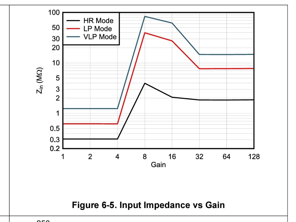
    at a PGA=8 setting, the ADS131M02 has a typical input impedance around 1MOhm. If you calculate with a 900kOhm input impedance you would see the kind of decrease in sensor output voltage that you are reporting. So this seems to be expected behavior.

    Regards,
    Joachim Wuerker

  • Thanks, I was looking at this graph, shouldn't it be greater at PGA=8 in VLP? Is there any way to increase it to at least 5MOhm?

  • Hello Godziller,

    that is actually correct. In VLP with PGA=8 you should see very high input impedance.
    Let me discuss this within the team and get back to you.

    How do you actually apply the input signal? Is it a single-ended signal where the negative input is held at GND?

    Regards,
    Joachim Wuerker

  • Thanks, the signal is differential, but the common mode range is respected. I use an anti aliasing filter as suggested on datasheet. 

  • Hello Godziller,

    would it be possible for you to measure the output voltage droop with two different sensor output signals? Maybe one small and one large one?
    If you could test the behavior with the anti-aliasing filter resistors shorted that might be valuable information as well.
    Have you tried both channels already to see if the behavior is the same on both ADC channels?

    Regards,
    Joachim Wuerker

  • I cant test other sensors at the moment sadly, but i tried another one the other day with 13mV output and the drop was about the same percentage. I tried without anti aliasing resistor and nothing change and its almost the same in both channels (i usually use the 1).

  • Thanks for the update Godziller.

    What we try to figure out is if you are experiencing a pure gain error or if that is a combination of offset and gain error. Therefore it would be helpful to know the sensor output signal droop when the sensor outputs a very small and a very large signal.

    Are you using a Wheatstone bridge type sensor in your case? And if yes, what excitation voltage are you using for the bridge?

    We would have ADS131B02-Q1 to offer, which is almost identical to ADS131M02 but offers higher input impedance. However its absolute input voltage range is even more restrictive.

    Regards,
    Joachim Wuerker

  • Thanks I'll try to give you measures for an higher output sensor but usually the MAX is around 25mV. Yes its a Wheatstone bridge with 2.5V excitation. We are using 2.7V for AVDD so 2.4V drop in absolute is a bit of a problem. I would like to try to keep using this ADC if possible and i tried to buffer the input signal with an OP-AMP buffer like OPA2328 and OPA333 but both add offset voltage that is not linear so im not able to calibrate it out.

  • Hi Godziller,

    you are actually not meeting the input common-mode voltage requirements of ADS131M02 in your case.
    The common-mode output voltage of the bridge is at 1.25V when using a 2.5V excitation. However, the positive and negative analog inputs of ADS131M02 need to stay below (2.7V - 1.8V) = 0.9V when using PGA=8.

    Have you tried using PGA=4 even though the input impedance of ADS131M02 is quite low there?

    Regards,
    Joachim Wuerker

  • Well I measured the outputs refered to GND and they are both below 400mV so it should be fine, its a custom sensor. I tried all the PGA but nothing really changes, it only gets worse. I measured another sensor, the open output is 26,375mV, and with the ADC it becomes 26,320mV.

  • Thanks for the clarification. That is definitely not a regular full-bridge then.

    I am somewhat running out of ideas now. Are you sure the output impedance of the sensor is only 5kOhm? Do you have any more details about the output stage of the sensor you can share?
    How much does the output voltage droop change when you switch from PGA=8 to PGA=4?

    Regards,
    Joachim Wuerker

  • I tried with different PGAs:

    BASE: 26.377mV
    PGA 1: 26.128mV
    PGA 4: 26.131mV
    PGA 8: 26.317mV
    PGA 64: 26.353mV 

    I measured the impedance directly with the multimeter on the output wires and its always around 5k (4.5k-5.5k with different sensors). I cant share much at moment about the output stage sadly.

  • Thanks Godziller.

    The "trend" from PGA=1 to PGA=8 does at least in general follow the input impedance characteristic shown in Figure 6-5. But the actual impedance values would seem to be lower than shown in the figure. For PGA=64 we would expect the droop to be larger than with PGA=8, which is weird.

    Have you tried to accept that droop and just calibrate the offset and gain error using the conversion results of the ADS131M02?

    Regards,
    Joachim Wuerker

  • Yes, the problem is that the calibrator has low output impedance so even if I calibrate well I have te problem with the sensors. 

  • Hi Godziller,

    I am currently discussing within the team what else we can propose.

    Based on your measured values it actually seems like the connection of the sensor causes primarily an offset error (~51uV), and not a gain error, which is a little weird. The effect of the input impedance should primarily cause a gain error instead.

    I assume you don't have any option to calibrate the system while having an actual sensor with 0V output signal connected?

    Regards,
    Joachim Wuerker

  • Thats not easy, because my sensors have some uV outputs even when measuring 0. Maybe i can just connect the sensor and calibrate without exciting it.

  • I tried to calibrate with the sensor in series and with a 5kohm resistor. It still doesnt work because the effect of both resistor/sensor is not present when i calibrate the offset (0V) and its only present when calibrating the gain because im on my fullscale.

  • Hi Godziller,

    thanks a lot for the update.

    Even if your sensor outputs a few uV when it is supposed to output 0, would that be a problem if you calibrate that away as well? I would suspect this could be considered the offset of the sensor, which you might want to calibrate anyway?!?
    Means read the conversion result of the ADC when the sensor is supposed to output 0. The measured value will be you offset calibration value which would remove the offset of the sensor itself and also the offset error introduced by the connection of the sensor to the ADC.

    Based on the values you provided we believe you have more of an offset error which is independent of the output signal value of the sensor, than a gain error. We suspect that the common-mode input current could cause this offset.

    Regards,
    Joachim Wuerker

  • We usually dont do that, we calibrate 0V and fullscale with a calibrator because we have a lot of sensors and a lot of different machines so that its not doable during production stages. 

    I was reading the ADS131B02 datasheet and i saw that it has bigger input impedance when global chop mode is enabled. At the moment im using continuos-conversion mode but since i dont need fast measures its possible to use chop mode do increase the impedance?

  • Hi Godziller,

    unfortunately the input impedance of ADS131M02 does not increase when operating in global-chop mode, as it does in ADS131B02-Q1.

    Regards,
    Joachim Wuerker

  • Thanks, at this point im running out of ideas too. Do you have any buffer or specific ICs I can use to interface the sensors to the ADC to solve this problem? Do you think its possible to solve it with firmware? 

  • Hi Godziller,

    Joachim will come back next Tuesday, please allow a response delay from him.

    Regards,

    Dale

  • Sure, thanks for your time.

  • Hi Godziller,

    I am sorry for the delay here. I have been out of office for an extended weekend.
    Seems like you are in contact with Antonio now already. I suggest we continue the discussion through him then by email. I will close this thread for now.

    Regards,
    Joachim Wuerker

  • Sure, thanks a lot for your time.