This thread has been locked.

If you have a related question, please click the "Ask a related question" button in the top right corner. The newly created question will be automatically linked to this question.

ADS54J60EVM: ADS54J60EVM and THS4541RGTEVM issue

Part Number: ADS54J60EVM
Other Parts Discussed in Thread: THS4541RGTEVM, , ADS54J60, THS4541

Dear TI Reps,

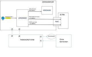
   We have interfaced ads54j60evm with ZC706 FPGA board and tested  successfully using TI BD design project with sine wave single ended i/p (both channel A and Channel B).  But as per our earlier discussions our requirement is to test the card for pulse(pulse width 20 ns and period 4 ms). In this regard we interfaced ads54j60evm with THS4541RGTEVM as per your earlier discussions we gave 100 ns pulse to the THS4541RGTEVM card(Single power supply mode) and connected differential o/p to ADS54J60EVM but no o/p was seen HSDC pro. HSDC pro always shows 245 MHz in FFT in all cases. In fact we tried with square wave i/p and results are same.                                                                   

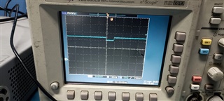
We have configured ADS54J60EVM as per inputs in TI forum for DC pulse. Please find the screenshots attach herewith.  Kindly suggest way for forward to resolve the issue.                                                                 
    Regards,
  • Hi Shambhuling,

    Just to confirm from your statement above, you are now trying to interface the THS4541 to the ADS54J60? Correct?

    If so, then you are not able to see the pulse that you are applying to the THS/ADS configuration?

    Would it be possible for you to share your full schematics, so that we can look at how this might be interfacing.

    also, it would be better to capture time domain data, rather than FFT data to show the pulse waveform being applied.

    Regards,

    Rob

  • Dear Rob,

      We are using TI made ADS54j60evm adc eval ,THS4541RGT EVM  eval board and also Xilinx made ZC706 FPGA Eval board for prototyping.               

    Please find the schematic diagram attached herewith. We have taken care ADS54J60EVM circuit changes recommended by your colleagues in the same thread related to Pulse input. Also THS amplifier card is modified as per user guide for differential outputs.

                We have seen time domain signal and no signal is found there. Any additional info required let me know.

    Also, we have tested only ADS54J60EVM card without amplifier board, Single ended signal was fed to channel A positive pin with Sine wave, Square wave and Pulse and found that circuit is working like High pass filter around 1 MHz. i.e If frequency of the signal is below 1 MHz signal is distorted in HSDC Pro. 

    Above 1 MHz signal is captured properly.

      Our requirement is capture Pulse with On time : 20 ns and Period : 1 sec to 5ms.

           I think this behaviour is due to cut-off frequencies of Balun and RC ckt present at analog front end.

      Please suggest the how to proceed further.

      Regards,

    Shambhuling D


  • Hi Shambhuling,

    Sorry for the delay, that is correct, if you plan to DC couple, then the balun needs to be removed.

    Otherwise, you won't be able to sample the pulse correctly.

    Regards,

    Rob